Sharp LC32E67U LC-32E67U Operation Manual - Page 42
RS-232C Port Specifications, PC control of the TV, Communication conditions, Communication procedure
 |
UPC - 074000371774
View all Sharp LC32E67U manuals
Add to My Manuals
Save this manual to your list of manuals |
Page 42 highlights
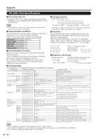
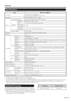
Appendix RS-232C Port Specifications ■ PC control of the TV • Attach an RS-232C cable cross-type (commercially available) to the supplied Din/D-Sub RS-232C for the connections. ■ Command format Eight ASCII codes e CR C1 C2 C3 C4 P1 P2 P3 P4 • This operation system should be used by a person who is accustomed to using computers. ■ Communication conditions Set the RS-232C communication settings on the PC to match the TV's communication conditions. The TV's communication settings are as follows: Baud rate: Data length: Parity bit: Stop bit: Flow control: 9,600 bps 8 bits None 1 bit None ■ Communication procedure Send the control commands from the PC via the RS232C connector. The TV operates according to the received command and sends a response message to the PC. Do not send multiple commands at the same time. Wait until the PC receives the OK response before sending the next command. Command 4-digits Parameter 4-digits Return code Command 4-digits: Command. The text of four characters. Parameter 4-digits: Parameter 0-9, x, blank, ? ■ Parameter Input the parameter values, aligning left, and fill with blank(s) for the remainder. (Be sure that 4 values are input for the parameter.) When the input parameter is not within an adjustable range, "ERR" returns. (Refer to "Response code format".) Any numerical value can replace the "x" on the table. 0 0009 a30 When "?" is input for some commands, the present setting ? value responds. ???? ■ Response code format Normal response OK Return code (0DH) Problem response (communication error or incorrect command) ERR Return code (0DH) ■ Command table • Commands not indicated here are not guaranteed to operate. CONTROL ITEM COMMAND PARAMETER CONTROL CONTENTS POWER ON COMMAND SETTING R S P W 0 _ _ _ Off The Power On command rejected. 1 _ _ _ On The Power On command accepted. POWER SETTING P O W R 0 _ _ _ Power Off It shifts to standby. 1 _ _ _ Power On Power On INPUT SELECTION A TOGGLE I T G D x _ _ _ (Toggle) It input-switches by the toggle. (It is the same as an input change key) TV I TVD0 _ _ _ It input-switches to TV. (A channel remains as it is. (Last memory)) INPUT1-8 INPUT SELECTION B INPUT 2 I A V D * _ _ _ Input terminal number (1-8) I N P 2 * _ _ _ 0: Auto, 2: COMPONENT, 3: S-TERMINAL It input-switches to INPUT1~INPUT8. An input change is also included. AV MODE SELECTION A V M D * _ _ _ 0: (Toggle), 1: STANDARD, 2: MOVIE, 3: GAME, 4: USER, Although it can choose now, it is toggle operation in inside. 5: DYNAMIC (Fixed), 6: DYNAMIC, 7: PC VOLUME V O L M * * _ _ Volume (0-60) POSITION H-POSITION H P O S * * * _ V-POSITION V P O S * * * _ When a DTV channel is selected, the horizontal position cannot be adjusted. The horizontal and/or vertical position may not be able to be adjusted or it may be adjusted only to a certain degree. VIEW MODE MUTE SURROUND AUDIO SELECTION SLEEP TIMER CHANNEL CC CLOCK PHASE DIRECT CHANNEL (ANALOG) DIRECT CHANNEL (DIGITAL) CH UP CH DOWN C L C K * * * _ Only PC mode. (0-180) P H S E * * * _ Only PC mode. (0-15) W I D E * _ _ _ 0: (Toggle) [AV], 1: Side Bar [AV], 2: S.Stretch [AV] 3: Zoom [AV], 4: Stretch [AV], 5: Normal [PC] 6: Zoom [PC], 7: Stretch [PC], 8: Dot by Dot [PC] [AV], 9: Full Screen [AV] 0: Although it can choose now, it is toggle operation in inside. 1: Only available when 4:3 signal is being input. 5, 6: Only available when 4:3 signal is being input. 8: [PC] Available except when UXGA is being input. [AV] Only available when 1080i/p is being input. 9: Only available when 720p is being input. M U T E * _ _ _ 0: (Toggle), 1: On, 2: Off A C S U * _ _ _ 0: (Toggle), 1: On, 2: Off A C H A x _ _ _ (Toggle) O F T M * _ _ _ 0: Off, 1: OFF TIMER - 30 MIN., 2: OFF TIMER - 60 MIN., 3: OFF TIMER - 90 MIN., 4: OFF TIMER - 120 MIN. D C C H * * * _ The channel number of TV (1-135) An input change is included if it is not TV display. In Air, 2-69ch is effective. In Cable, 1-135ch is effective. D A 2 P * * * * (0100-9999) DIGITAL Air (Two-Part numbers, 2-digit plus 2-digit) D C 2 U * * * _ (1-999) DIGITAL Cable (Two-Part numbers, 3-digit plus 3-digit) Front half of DIGITAL CABLE CHANNEL NO. (Designate major channel) D C 2 L * * * _ (0-999) DIGITAL Cable (Two-Part numbers, 3-digit plus 3-digit) Rear half of DIGITAL CABLE CHANNEL NO. (Designate minor channel) D C 1 0 * * * * (0-9999) D C 1 1 * * * * (0-6383) C H U P x _ _ _ The channel number of TV +1 C H D W x _ _ _ The channel number of TV -1 C L C P x _ _ _ (Toggle) DIGITAL Cable (One-Part numbers, 5-digit, less than 10,000) DIGITAL Cable (One-Part numbers, 5-digit, more than 10,000) If it is not TV display, it will input-switch to TV. (same function as CHU) If it is not TV display, it will input-switch to TV. (same function as CHV) Toggle operation of a closed caption. • If an underbar (_) appears in the parameter column, enter a space. • If an asterisk (*) appears, enter a value in the range indicated in brackets under CONTROL CONTENTS. • Any numerical value can replace the "x" on the table. 40
-
 1
1 -
2
-
3
-
4
-
5
-
6
-
7
-
8
-
9
-
10
-
11
-
12
-
13
-
14
-
15
-
16
-
17
-
18
-
19
-
20
-
21
-
22
-
23
-
24
-
25
-
26
-
27
-
28
-
29
-
30
-
31
-
32
-
33
-
34
-
35
-
36
-
 37
37 -
 38
38 -
 39
39 -
 40
40 -
 41
41 -
 42
42 -
 43
43 -
 44
44 -
 45
45 -
 46
46 -
 47
47
 |
 |