Sharp LC32SB23U Operation Manual - Page 10
Part Names - tv lc
 |
View all Sharp LC32SB23U manuals
Add to My Manuals
Save this manual to your list of manuals |
Page 10 highlights
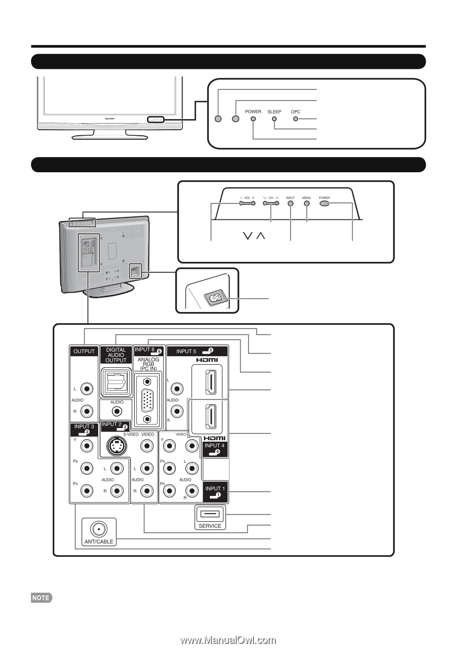
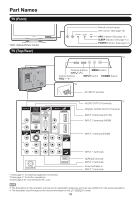
Part Names TV (Front) *OPC: Optical Picture Control TV (Top/Rear) Remote control sensor OPC sensor* (See page 18.) OPC indicator (See page 18.) SLEEP indicator (See page 13.) POWER indicator (See page 12.) *2 Channel buttons MENU button (CHV/U) Volume buttons INPUT button POWER button (VOLl/k) *3 AC INPUT terminal *1 AUDIO OUTPUT terminals DIGITAL AUDIO OUTPUT terminal INPUT 6 terminals (PC-IN) INPUT 5 terminals (HDMI) INPUT 4 terminal (HDMI) *1 See page 11 for external equipment connection. *2 See page 17 for button operations. *3 See page 8 for connecting the AC cord. INPUT 1 terminals SERVICE terminal INPUT 2 terminals Antenna/Cable in INPUT 3 terminals • The illustrations in this operation manual are for explanation purposes and may vary slightly from the actual operations. • The examples used throughout this manual are based on the LC-32SB23U model. 10
-
 1
1 -
2
-
3
-
4
-
 5
5 -
 6
6 -
 7
7 -
 8
8 -
 9
9 -
 10
10 -
 11
11 -
 12
12 -
 13
13 -
 14
14 -
 15
15 -
16
-
17
-
18
-
19
-
20
-
21
-
22
-
23
-
24
-
25
-
26
-
27
-
28
-
29
-
30
-
31
-
32
 |
 |