Sharp R-209FW Service Manual - Page 13
High Voltage Transformer Test, Caution: 1
 |
View all Sharp R-209FW manuals
Add to My Manuals
Save this manual to your list of manuals |
Page 13 highlights
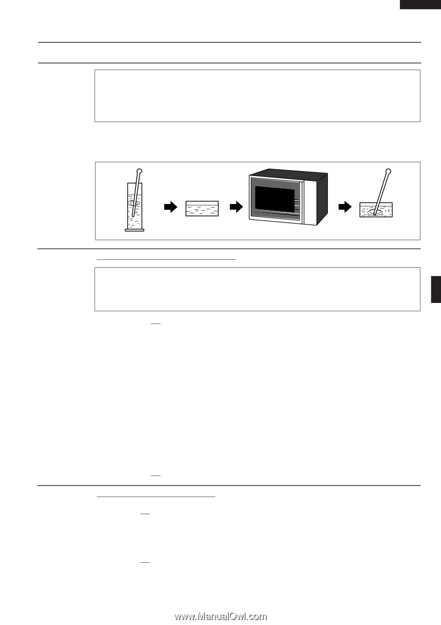
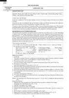
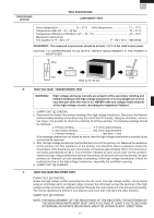
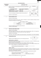
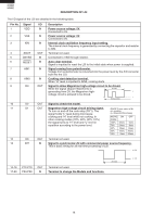
PROCEDURE LETTER TEST PROCEDURES COMPONENT TEST R-209(IN) R-209(W) R-209(Y) Room temperature To = 21˚C Initial temperature T1 = 11°C Temperature after (52 + 3) = 55 sec T2 = 21°C Temperature difference Cold-Warm (∆T = T2 - T1 T = 10°C Measured output power The equation is "P = 80 x ∆T P = 80 x 10°C = 800 Watts JUDGEMENT: The measured output power should be at least ± 15 % of the rated output power. CAUTION: 1°C CORRESPONDS TO 80 WATTS. REPEAT MEASUREMENT IF THE POWER IS INSUFFICIENT. 1000g 1000g 1000g T1˚C T2˚C Heat up for 55 sec. B HIGH VOLTAGE TRANSFORMER TEST WARNING: High voltage and large currents are present at the secondary winding and filament winding of the high voltage transformer. It is very dangerous to work near this part when the oven is on. NEVER make any voltage measurements of the high-voltage circuits, including the magnetron filament. 1. CARRY OUT 3D CHECKS. 2. Disconnect the leads to the primary winding of the high voltage transformer. Disconnect the filament and secondary winding connections from the rest of the HV circuitry. Using an ohmmeter, set on a low range, it is possible to check the continuity of all three winding. The following readings should be obtained:- a. Primary winding 2.7 ohms approximately b. Secondary winding 205 ohms approximately c. Filament winding less than 1 ohm If the readings obtained are not stated as above, then the high voltage transformer is probably faulty and should be replaced. 3. Also, the high voltage transformer has the thermal cut-out in the primary coil. Measure the resistance of the primary coil. The resistance of the primary coil should be above resistance unless the temperature of the thermal cut-out in the primary coil reaches approximately 150˚C. The thermal cutout resets automatically at 130˚C. If an ohmmeter indicates an open circuit under normal condition, replace the high voltage transformer because the primary coil (thermal cut-out) has opened. An open primary coil (thermal cut-out) indicates overheating of the high voltage transformer. Check for restricted air flow to the high voltage transformer, especially the ventilation opening. 4. CARRY OUT 4R CHECKS. C HIGH VOLTAGE RECTIFIER TEST CARRY OUT 3D CHECKS. Isolate the high voltage rectifier assembly from the HV circuit. The high voltage rectifier can be tested using an ohmmeter set to its highest range. Connect the ohmmeter across the terminal of the high voltage rectifier and note the reading obtained. Reverse the meter leads and note this second reading. The normal resistance is infinite in one direction and more than 100 kΩ in the other direction. CARRY OUT 4R CHECKS. NOTE: FOR MEASUREMENT OF THE RESISTANCE OF THE RECTIFIER, THE BATTERIES OF THE MEASURING INSTRUMENT MUST HAVE A VOLTAGE AT LEAST 6 VOLTS, BECAUSE OTHERWISE AN INFINITE RESISTANCE MIGHT BE SHOWN IN BOTH DIRECTIONS. 11
-
 1
1 -
2
-
3
-
4
-
5
-
6
-
7
-
 8
8 -
 9
9 -
 10
10 -
 11
11 -
 12
12 -
 13
13 -
 14
14 -
 15
15 -
 16
16 -
 17
17 -
 18
18 -
19
-
20
-
21
-
22
-
23
-
24
-
25
-
26
-
27
-
28
-
29
-
30
-
31
-
32
-
33
-
34
-
35
-
36
 |
 |