Sharp R-209FW Service Manual - Page 16
Control Unit Test, Relay Test - microwave model
 |
View all Sharp R-209FW manuals
Add to My Manuals
Save this manual to your list of manuals |
Page 16 highlights
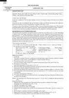
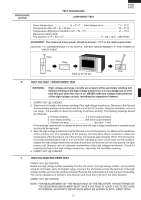
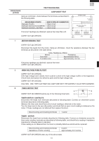
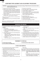
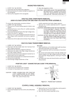
R-209(IN) R-209(W) R-209(Y) PROCEDURE LETTER L CONTROL UNIT TEST TEST PROCEDURES COMPONENT TEST CAUTION: DO NOT TOUCH THE ELECTRICAL PARTS AND THE PRINTED WIRING BOARD TO PREVENT AN ELECTRIC SHOCK. BECAUSE THE CONTROL UNIT IS " TRANSLESS CIRCUIT " AND ALL ELECTRICAL PARTS ARE USED AT A.C. LINE VOLTAGE. The control unit consists of circuits including semiconductors such as LSI, etc. Therefore, unlike conventional microwave ovens, proper maintenance can not be performed with only a voltmeter and ohmmeter. In this service manual, troubleshooting by unit replacement is described according to the symptoms indicated. Control unit. The following symptoms indicate a defective control unit. a) When rotating the potentiometer, the power level can not be selected. b) Cooking is not possible. M RELAY TEST CARRY OUT 3D CHECKS. Remove the outer case and check voltage between Pin No. 3 of the 2 pin connector (A) and the common terminal of the relay RY1 on the control unit with an A.C. voltmeter. The meter should indicate 230 volts, if not check oven circuit. Relay Test Check voltage at the relay coil with a D.C. voltmeter during the microwave cooking operation. DC. voltage indicated .......... Defective relay. DC. voltage not indicated .... Check diode which is connected to the relay coil. If diode is good, control unit is defective. RELAY SYMBOL RY1 RY2 OPERATIONAL VOLTAGE Approx. 12.0V D.C. Approx. 11.0V D.C. CONNECTED COMPONENTS Oven lamp / Turntable motor / Fan motor High voltage transformer CARRY OUT 4R CHECKS. N PROCEDURES TO BE TAKEN WHEN THE FOIL PATTERN ON THE PRINTED WIRING BOARD (PWB) IS OPEN To protect the electronic circuits, this model is provided with a fine foil pattern added to the input circuit on the PWB, this foil pattern acts as a fuse. If the foil pattern is open, follow the troubleshooting guide given below for repair. Problem: POWER ON. CARRY OUT 3D CHECKS. STEPS 1 2 3 OCCURRENCE The rated voltage is not applied between Pin No. 3 of the 2 pin connector (A) and the common terminal of the relay RY1. Only pattern at "a" is broken. Pattern at "a" and "b" are broken. CAUSE OR CORRECTION Check supply voltage and oven power cord. *Insert jumper wire J1 and solder. *Insert the coil RCILF2003YAZZ between "c" and "d". (F1) NOTE: *At the time of making these repairs, make a visual inspection of the varistor. Check for burned damage. If any abnormal condition is detected, replace the defective parts. CARRY OUT 4R CHECKS. d c a (J1) D70 b D1 (J2) D71 R75 14
-
 1
1 -
2
-
3
-
4
-
5
-
6
-
7
-
8
-
9
-
10
-
 11
11 -
 12
12 -
 13
13 -
 14
14 -
 15
15 -
 16
16 -
 17
17 -
 18
18 -
 19
19 -
 20
20 -
 21
21 -
22
-
23
-
24
-
25
-
26
-
27
-
28
-
29
-
30
-
31
-
32
-
33
-
34
-
35
-
36
 |
 |