Sharp R-209FW Service Manual - Page 17
CONTROL UNIT ASSEMBLY, OUTLINE OF CONTROL UNIT, Control Unit, Reset Circuit, Potentiometer Circuit
 |
View all Sharp R-209FW manuals
Add to My Manuals
Save this manual to your list of manuals |
Page 17 highlights
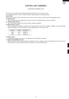
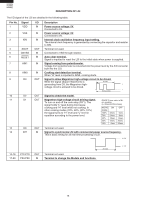
CONTROL UNIT ASSEMBLY OUTLINE OF CONTROL UNIT R-209(IN) R-209(W) R-209(Y) The control unit consists of the following circuits as shown in the control unit circuit. The principal functions of these circuits and their related signals are explained below. Control Unit Control unit consists of LSI, reset circuit, power source circuit, relay circuit and synchronizing signal circuit. 1) Reset Circuit This circuit generates a signal which resets the LSI to the initial state when power is supplied. 2) Potentiometer Circuit The circuit makes setting of the power level by variable resistance. 3) Power Source Circuit This circuit generates voltage necessary in the control unit from the AC line voltage. In addition, the synchronizing signal is available in order to compose a basic standard time in the clock circuit. Symbol VDD VSS Voltage +5V 0V Application LSI(IC-1) LSI(IC-1) 4) Relay Circuit To drive the magnetron, fan motor, turntable motor and light the oven lamp. 5) Synchronizing Signal Circuit The power source synchronizing signal is available in order to compose a basic standard time in the clock circuit. It accompanies a very small error because it works on commercial frequency. 15
-
 1
1 -
2
-
3
-
4
-
5
-
6
-
7
-
8
-
9
-
10
-
11
-
 12
12 -
 13
13 -
 14
14 -
 15
15 -
 16
16 -
 17
17 -
 18
18 -
 19
19 -
 20
20 -
 21
21 -
 22
22 -
23
-
24
-
25
-
26
-
27
-
28
-
29
-
30
-
31
-
32
-
33
-
34
-
35
-
36
 |
 |