Sharp R-209FW Service Manual - Page 23
Power Supply Cord Replacement, Monitored Latch Switch (sw1)
 |
View all Sharp R-209FW manuals
Add to My Manuals
Save this manual to your list of manuals |
Page 23 highlights
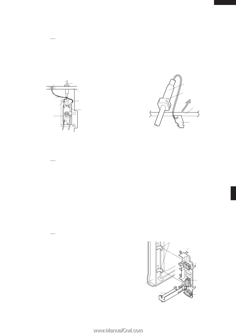
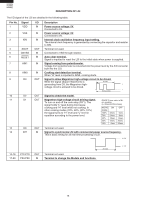
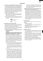
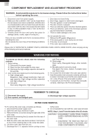
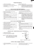
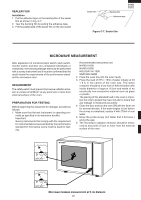
POWER SUPPLY CORD REPLACEMENT R-209(IN) R-209(W) R-209(Y) Removal 1. CARRY OUT 3D CHECKS. 2. Remove the single (1) screw holding the green/yellow wire to the oven cavity. 3. Disconnect the leads of the power supply cord from the noise filter, referring to the Figure C-3 (a). 4. Release the moulding cord stopper of the power supply cord from the square hole of the oven cavity back plate, referring to the Figure C-3 (b). 5. Now, the power supply cord is free. Screw Power Supply Cord Green/Yelow Wire Blue Wire Noise Filter Oven Cavity Back Plate Brown Wire Fuse Re-install 1. Insert the moulding cord stopper of power supply cord into the square hole of the rear cabinet, referring to the Figure C-3 (b). 2. Install the earth wire lead of power supply cord and the earth angle to the oven cavity with one (1) screw and tight the screw. 3. Connect the brown and blue wire leads of power supply cord to the noise filter correctly, referring to the Pictorial Diagram. Power Supply Cord Moulding Cord Stopper Oven Cavity Back Plate Square Hole Figure C-3 (a). Power Supply Cord Replacement Figure C-3 (b) Power Supply Cord Replacement MONITORED LATCH SWITCH (SW1), LATCH SWITCH (SW3) AND MONITOR SWITCH (SW2) REMOVAL 1. CARRY OUT 3D CHECKS. 2. Disconnect wire leads from the switches. 3. Remove two (2) screws holding latch hook to oven flange. 4. Remove the switch lever from the oven cavity 5. Remove latch hook assembly from oven flange. 6. Push outward on the two (2) retaining tabs holding switch in place. 7. Switch is now free. Re-install 1. Re-install each switch in its place. The latch/monitor switches are in the lower position and the monitored latch switch is in the upper position. 2. Re-connect wire leads to each switch. Refer to pictorial diagram. 3. Secure latch hook (with two (2) mounting screws) to oven flange. 4. Install the switch lever to the oven cavity 5. Make sure that the monitor switch is operating properly and check continuity of the monitor circuit. Refer to chapter "Test Procedure" and Adjustment procedure. MONITORED LATCH SWITCH (SW1), LATCH SWITCH (SW3) AND MONITOR SWITCH (SW2) ADJUSTMENT 1. CARRY OUT 3D CHECKS. If the monitored latch switch, latch switch and monitor switch do not operate properly due to a misadjustment, the following adjustment should be made. 2. Loosen the two (2) screws holding latch hook to the oven cavity front flange. 3. With door closed, adjust latch hook by moving it back and forth, and up and down. In and out play of the door allowed by the upper and lower position of the latch hook should be less than 0.5mm. The vertical position of the latch hook should be adjusted so that the monitored latch switch and latch switch are activated with the door closed. The horizontal position of the latch hook should be adjusted so that the plunger of the monitor switch is pressed with the door closed. 4. Secure the screws with washers firmly. 5. Check the operation of all switches. If each switch has not activated with the door closed, loosen screw and adjust the latch hook position. Latch Heads Latch Hook Door Switch Lever SW1: Monitored Latch Switch SW2: Monitor Switch SW3: Latch Switch Figure C-4. Latch Switch Adjustments 21
-
 1
1 -
2
-
3
-
4
-
5
-
6
-
7
-
8
-
9
-
10
-
11
-
12
-
13
-
14
-
15
-
16
-
17
-
 18
18 -
 19
19 -
 20
20 -
 21
21 -
 22
22 -
 23
23 -
 24
24 -
 25
25 -
 26
26 -
 27
27 -
 28
28 -
29
-
30
-
31
-
32
-
33
-
34
-
35
-
36
 |
 |