Sharp R-209FW Service Manual - Page 24
DOOR REPLACEMENT, C-5. Door Disassembly
 |
View all Sharp R-209FW manuals
Add to My Manuals
Save this manual to your list of manuals |
Page 24 highlights
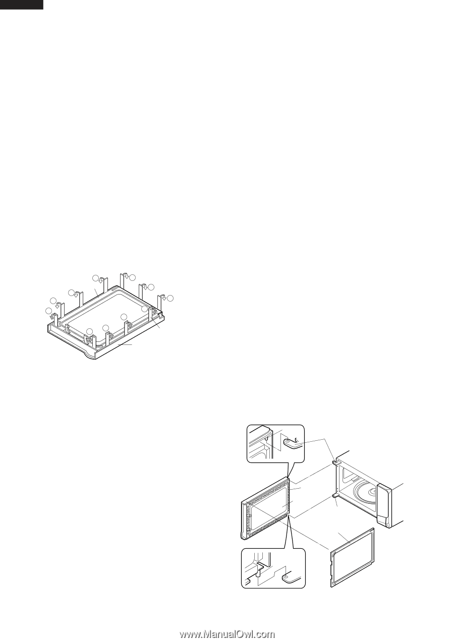
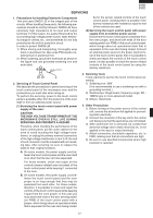
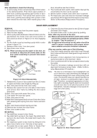
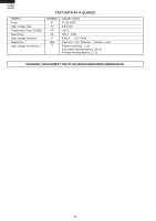
R-209(IN) R-209(W) R-209(Y) After adjustment, check the following. 1. In and out play of door remains less than 0.5mm when in the latched position. First check upper position of latch hook, pushing and pulling upper portion of door toward the oven face. Then check lower portion of the latch hook, pushing and pulling lower portion of the door toward the oven face. Both results (play in the door) should be less than 0.5mm. 2. The monitored latch switch, latch switch interrupt the circuit before the door can be opened. 3. Monitor switch contacts close when door is opened. 4. Re-install outer case and check for microwave leakage around door with an approved microwave survey meter. (Refer to Microwave Measurement Procedure.) DOOR REPLACEMENT REMOVAL 1. Disconnect the oven from the power supply. 2. Open the door slightly. 3. Insert a putty knife (thickness of about 0.5mm) into the gap between the choke cover and corner portion of door panel as shown in Figure C-5 to free engaging parts. 4. Pry the choke cover by inserting a putty knife in order shown in figure C-5. 5. Release choke cover from door panel. 6. Now choke cover is free. NOTE: When carrying out any repair to the door, do not bend or warp the slit choke (tabs on the door panel assembly) to prevent microwave leakage. 8 Choke Cover 7 6 5 3 4 9 10 11 1 2 Putty Knife Door Frame Figure C-5. Door Disassembly 7. Release two (2) pins of door panel from two (2) holes of upper and lower oven hinges by lifting up. 8. Now, door panel is free from oven cavity. 9. Release door panel from ten (10) tabs of door frame and remove door frame by sliding the door panel downward. 10.Now, door panel with sealer film is free. 11.Tear sealer film from door panel. 12.Now, door panel is free. 13.Slide latch head upward and remove it from door frame with releasing latch spring from door frame and latch head. 14.Now, latch head and latch spring are free. 15.Remove door screen from door frame. 16.Now, door screen is free. RE-INSTALL 1. Re-install door screen to door frame. 2. Re-install latch spring to the head. Re-install latch spring to the door frame. Re-install latch head to the door frame. 3. Re-install door panel to door frame by fitting ten (10) tabs of door frame to ten (10) holes of door panel. 4. Put sealer film on door panel. Refer to "Sealer Film" and figure C-7, on how to handle the new film. 5. Catch two (2) pins of door panel on two (2) hole of upper and lower oven hinges. 6. Re-install choke cover to door panel by pushing. Note: After any service to the door; (A) Make sure that monitored latch switch, latch switch and monitor switch are operating properly. (Refer to chapter "Test Procedures".). (B) An approved microwave survey meter should be used to assure compliance with proper microwave radiation emission limitation standards. After any service, make sure of the following : 1. Door latch heads smoothly catch latch hook through latch holes and that latch head goes through center of latch hole. 2. Deviation of door alignment from horizontal line of cavity face plate is to be less than 1.0mm. 3. Door is positioned with its face pressed toward cavity face plate. 4. Check for microwave leakage around door with an approved microwave survey meter. (Refer to Microwave Measurement Procedure.) Note: The door on a microwave oven is designed to act as an electronic seal preventing the leakage of microwave energy from oven cavity during cook cycle. This function does not require that door be air-tight, moisture (condensation)-tight or lighttight. Therefore, occasional appearance of moisture, light or sensing of gentle warm air movement around oven door is not abnormal and do not of themselves, indicate a leakage of microwave energy from oven cavity. Pin Upper Oven Hinge Slit Choke Door Panel Lower Oven Hinge Choke Cover Lower Pin Oven Hinge Figure C-6. Door Replacement 22
-
 1
1 -
2
-
3
-
4
-
5
-
6
-
7
-
8
-
9
-
10
-
11
-
12
-
13
-
14
-
15
-
16
-
17
-
18
-
 19
19 -
 20
20 -
 21
21 -
 22
22 -
 23
23 -
 24
24 -
 25
25 -
 26
26 -
 27
27 -
 28
28 -
 29
29 -
30
-
31
-
32
-
33
-
34
-
35
-
36
 |
 |