Sharp R-209FW Service Manual - Page 9
Operation Sequence, Off Condition, Microwave Cooking Condition, Power Level Cooking
 |
View all Sharp R-209FW manuals
Add to My Manuals
Save this manual to your list of manuals |
Page 9 highlights
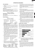
OPERATION SEQUENCE R-209(IN) R-209(W) R-209(Y) OFF CONDITION 1. When the timer knob is at " ", the oven is OFF condition. 2. Closing the oven door activates the monitored latch switch and the latch switch. IMPORTANT When the oven door is closed, the contacts (COM-NC) of the monitor switch SW2 must be open. When the microwave oven is plugged in a wall outlet, rated voltage is supplied to the noise filter and the control unit. Figure O-1 on page 25 MICROWAVE COOKING CONDITION HIGH COOKING Set the Microwave power control knob to then set the timer. 800W and Function sequence Figure O-2 on page 25 1. Following components are energized. High voltage rectifier High voltage transformer High voltage capacitor High voltage fuse Turntable motor Timer motor Fan motor Magnetron Oven lamp Control unit CONNECTED COMPONENTS RELAY High voltage transformer RY1 2. Rated voltage is supplied to the primary winding of the high voltage transformer T. The voltage is converted to about 3.3 volts A.C. output on the filament winding and high voltage of approximately 2000 volts A.C. on the secondary winding. 3. The filament winding voltage (3.3 volts) heats the magnetron filament and the high voltage (2000 volts) is sent to the voltage doubling circuit, where it is doubled to negative voltage of approximately 4000 volts D.C.. 4. The 2450 MHz microwave energy produced in the magnetron MG generates a wave length of 12.24 cm. This energy is channelled through the waveguide (transport channel) into the oven cavity, where the food is placed to be cooked. 5. When the cooking time is up, the timer returns to " ", the bell rings and the contacts of the timer switch are opened. The following components are turned off. High voltage rectifier High voltage transformer High voltage capacitor High voltage fuse Turntable motor Timer motor Fan motor Magnetron Oven lamp Control unit 6. When the oven door is opened during a cook cycle, the switches come to the following position and they are common to the other cooking conditions too. SWITCH CONTACT Monitored latch switch COM-NO CONDITION DURING DOOR OPEN COOKING (NO COOKING) Closed Open Latch switch Monitor switch COM-NO Closed COM-NC Open Open Closed The circuits to the high voltage transformer T, turntable motor TTM, timer motor TM, fan motor FM, oven lamp OL and control unit are cut off when the contacts (COM-NO) of the monitored latch switch SW1 and latch switch SW3 are made open. The timer stops to indicate how much cooking time remains. 7. MONITOR SWITCH CIRCUIT The monitor switch SW2 is mechanically controlled by oven door, and monitors the operation of the monitored latch switch SW1. 7-1 When the oven door is opened during or after the cycle of a cooking program, the monitored latch switch SW1 and latch switch SW3 must open their contacts (COM-NO) first. After that the contacts (COMNC) of the monitor switch SW2 can be closed. 7-2. When the oven door is closed, the contacts (COMNC) of the monitor switch SW2 must be opened first. And then the contacts (COM-NO) of the monitored latch switch SW1 and the latch switch SW3 are closed. 7-3. When the oven door is opened and the contacts (COM-NO) of the monitored latch switch SW1 and contacts of the timer switch remain closed. The fuse F1 T6.3A will blow, because the monitor switch is closed and a short circuit is caused. POWER LEVEL COOKING When the microwave oven is preset for variable cooking power, rated voltage is supplied to the high voltage transformer intermittently within a 32-second time base through the relay contact which is coupled with the current-limiting relay. The following levels of microwave power are given. SETTING; 32 sec. ON 800W 24 sec. ON 560W 18 sec. ON 400W 12 sec. ON 240W 6 sec. ON 80W 100% 8 sec. OFF Approx. 70% 14 sec. OFF Approx. 50% 10 sec. OFF Approx. 30% 26 sec. OFF Approx. 10% NOTE: The ON/OFF time ratio does not exactly correspond to the percentage of microwave power, because approx. 3 seconds are needed for heating up the magnetron filament. POWER OUTPUT REDUCTION 1. If the oven is set for more than 20 minutes at 800W, after the first 20 minutes the power level will automatically adjust itself to 70% power to avoid overcooking. 2. If the oven is operated for more than 90 minutes continuously (at any power levels), the relay RY1 opens. And the circuit to the high voltage transformer will be cut off. 7
-
 1
1 -
2
-
3
-
 4
4 -
 5
5 -
 6
6 -
 7
7 -
 8
8 -
 9
9 -
 10
10 -
 11
11 -
 12
12 -
 13
13 -
 14
14 -
15
-
16
-
17
-
18
-
19
-
20
-
21
-
22
-
23
-
24
-
25
-
26
-
27
-
28
-
29
-
30
-
31
-
32
-
33
-
34
-
35
-
36
 |
 |