Sharp R930AK Service Manual
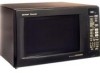
Sharp R930AK - 1.5 CF 900 Watts Convection Sensor Interactive; Charcoal Manual
 |
UPC - 074000606036
View all Sharp R930AK manuals
Add to My Manuals
Save this manual to your list of manuals |
Sharp R930AK manual content summary:
- Sharp R930AK | Service Manual - Page 1
CONVECTION MICROWAVE OVEN MODELS R-930AK R-930AW In the interest of user-safety the oven should be restored to its original condition and only parts identical to those specified should be used. TABLE OF CONTENTS Page PRECAUTIONS TO BE OBSERVED BEFORE AND DURING SERVICE TO AVOID POSSIBLE EXPOSURE - Sharp R930AK | Service Manual - Page 2
or misadjusted components in the interlock, monitor, door seal, and microwave generation and transmission systems shall be repaired, replaced, or adjusted by procedures described in this manual before the oven is released to the owner. (e) A microwave leakage check to verify compliance with the - Sharp R930AK | Service Manual - Page 3
R-930AK R-930AW BEFORE SERVICING Before servicing an operative unit, perform a microwave emission check as per the Microwave Measurement Procedure outlined in this service manual. If microwave emissions level is in excess of the specified limit, contact SHARP ELECTRONICS CORPORATION immediately 1- ( - Sharp R930AK | Service Manual - Page 4
R-930AK R-930AW MICROWAVE MEASUREMENT PROCEDURE A. Requirements: 1) Microwave leakage limit (Power density limit): The power density of microwave radiation emitted by a microwave oven should not exceed 1mW/cm2 at any point 5cm or more from the external surface of the oven, measured prior to - Sharp R930AK | Service Manual - Page 5
SERVICE MANUAL CONVECTION MICROWAVE OVEN R-930AK / R-930AW FOREWORD This Manual has been prepared to provide Sharp Electronics Corp. Service Personnel with Operation and Service Information for the SHARP CONVECTION MICROWAVE OVENS R930AK / R-930AW. It is recommended that service personnel carefully - Sharp R930AK | Service Manual - Page 6
Output Case Dimensions Cooking Cavity Dimensions (1.5 Cubic Feet ) Control Complement Oven Cavity Light Safety Standard SPECIFICATION DESCRIPTION 120 Volts 13.0 Amperes (Microwave) / 13.0 Amperes (Convection) 60 Hertz / Single phase, 3 wire grounded 900 watts (IEC 705 Test Procedure) Operating - Sharp R930AK | Service Manual - Page 7
1. Ventilation openings. (Rear side) 7. Wave guide cover. 2. Oven door with see-through window. 8. Door open button. 3. Oven lamp. 9. Auto-Touch control panel. 4. Turntable support. 10. Lighted digital display. 5. Removable turntable. 11. Convection air openings. The turntable will rotate - Sharp R930AK | Service Manual - Page 8
microwave energy is stopped. The oven will revert to the OFF condition. 6. When the door is opened during a cook cycle, monitor switch, door sensing switch, the primary interlock relay and the secondary interlock switch are activated with the following results. The circuits to the turntable motor - Sharp R930AK | Service Manual - Page 9
on the oven lamp, turntable motor, cooling fan motor and convection fan motor. 3. The shut-off relay (RY4) is energized. The damper door is MICRO.) ON OFF MICROWAVE POWER = APPROX. 10% (CONVEC.) LOW MIX BAKE CONVECTION TEMPERATUE = 350˚F (180˚C) (MICRO.) 12 SEC. ON 20 SEC. OFF MICROWAVE - Sharp R930AK | Service Manual - Page 10
, turning on the oven lamp, turntable motor, cooling fan motor and convection motor. The power supply voltage is applied to the heating element. 4. Now, the oven is in the convection cooking mode. 5. When the oven temperature has reached the programmed convection temperature, the oven goes into the - Sharp R930AK | Service Manual - Page 11
RECTIFIER MAGNETRON SCHEMATIC DIAGRAM SCHEMATIC NOTE: CONDITION OF OVEN 1. DOOR CLOSED. 2. CLOCK APPEARS ON DISPLAY. CONV. THERMAL CUT-OUT MAGNETRON TEMPERATURE FUSE MONITOR SWITCH FUSE OUTER CASE SWITCH TTM OL FM CM DM TURNTABLE MOTOR OVEN LAMP FAN MOTOR CONVECTION MOTOR DAMPER MOTOR 120V - Sharp R930AK | Service Manual - Page 12
R-930AK R-930AW SCHEMATIC 1. DOOR CLOSED. 2. MIX COOKING PAD TOUCHED. 3. COOKING TIME PROGRAMMED. 4. "START" PAD TOUCHED. 5. RY2 AND RY3 WILL ALTERNATELY CLOSE. DURING COOK CYCLE. CONV. THERMAL CUT-OUT MAGNETRON TEMPERATURE FUSE FUSE OUTER CASE SWITCH TTM OL FM CM DM TURNTABLE MOTOR OVEN LAMP - Sharp R930AK | Service Manual - Page 13
R-930AK R-930AW DESCRIPTION AND FUNCTION OF COMPONENTS DOOR SENSING AND SECONDARY INTERLOCK SWITCHES The door DOOR SENSING SWITCH MONITOR FUSE MONITOR SWITCH SECONDARY INTERLOCK SWITCH OUTER CASE SWITCHES The two outer case switches are mounted near the power supply cord at the oven cavity rear - Sharp R930AK | Service Manual - Page 14
damper door is not in the proper position, closed during convection or open during microwave, the control unit will stop oven operation after 1 minute. DAMPER SHAFT DAMPER DUCT DAMPER DAMPER CAM DAMPER SWITCH DAMPER MOTOR Figure D-2. Damper Mechanism TROUBLESHOOTING GUIDE When troubleshooting the - Sharp R930AK | Service Manual - Page 15
RY-5 RELAY RY-6 FOIL PATERN ON PWB. AH SENSOR OVEN LAMP OR SOCKET FAN MOTOR TURNTABLE MOTOR CONVECTION MOTOR LOOSE WIRING SHORTED IN POWER CORD NO POWER AT OUTLET LOW VOLTAGE CONDITION OFF CONDITION COOKING CONDITION 13 TEST PROCEDURE PROBLEM Home fuse blows when power cord is plugged into wall - Sharp R930AK | Service Manual - Page 16
930AK R-930AW PROCEDURE LETTER TEST PROCEDURES COMPONENT TEST A MAGNETRON ASSEMBLY TEST HIGH VOLTAGES ARE PRESENT DURING THE COOK CYCLE, SO EXTREME CAUTION SHOULD BE OBSERVED. DISCHARGE THE HIGH VOLTAGE CAPACITOR BEFORE TOUCHING ANY OVEN is grounded and must be replaced. Power output of the - Sharp R930AK | Service Manual - Page 17
930AK R-930AW the front plate of the oven cavity with the door opened (in this condition DOOR SENSING SWITCH AND MONITOR SWITCH FOR PROPER OPERATION. If the monitor fuse is blown by improper switch operation, the monitor fuse and switch must be replaced with "monitor fuse and switch assembly" part - Sharp R930AK | Service Manual - Page 18
under the normal condition, replace the same item as in the parts list. An open thermal cut-out indicates overheating of heater unit. Check for restricted air flow to the heater unit through the vent hole of the oven cavity, especially the heater duct and convection fan. K HEATING ELEMENT TEST - Sharp R930AK | Service Manual - Page 19
. Therefore, unlike conventional microwave ovens, proper maintenance cannot be performed with only a voltmeter and ohmmeter. In this service manual, the touch control panel assembly is divided into two units, Control Unit and Key Unit and troubleshooting by unit replacement is described according to - Sharp R930AK | Service Manual - Page 20
Approx. 19.0V D.C. Heating element Damper motor RY5 Approx. 19.0V D.C. Convection motor RY6 Approx. 19.0V D.C. Cooling fan motor T COMPU DEFROST TEST (1) Place one cup of water in the center of the turntable tray in the oven cavity. (2) Close the door, touch the "COMPU DEFROST" pad twice - Sharp R930AK | Service Manual - Page 21
R-930AK R-930AW PROCEDURE LETTER TEST PROCEDURES COMPONENT TEST Problem: POWER ON, indicator does not light up. STEPS detected, replace the defective parts. POWER 7 5 3 d b a c 3 T1 (J1) 26 CN - A 9 V AH SENSOR TEST Checking the initial sensor cooking condition (1) The oven should be - Sharp R930AK | Service Manual - Page 22
930AK R-930AW PROCEDURE LETTER TEST PROCEDURES COMPONENT TEST NOTE: ERROR will appear if the door is opened or STOP/CLEAR pad is touched during first stage of sensor cooking. (6) After approximately 16 seconds, microwave is to replace it with a new replacement sensor. (1) Disconnect oven from - Sharp R930AK | Service Manual - Page 23
CONTROL PANEL ASSEMBLY OUTLINE OF TOUCH CONTROL PANEL R-930AK R-930AW The touch control section consists of the following if the door is open or closed. 9) Relay Circuit To drive the magnetron, heating element, fan motor, convection motor, damper motor, turntable motor and light the oven lamp. 10 - Sharp R930AK | Service Manual - Page 24
- P55 cent Display. Oven lamp and turntable motor driving signal. (Square Waveform : 60Hz) To turn on and off the shut-off relay(RY1). 16.7 msec. The square waveform voltage is delivered to H the relay(RY1) driving circuit. L During cooking 15 P53 OUT Convection motor driving signal. To - Sharp R930AK | Service Manual - Page 25
930AK R-930AW during microwave cooking sec. 32 sec. Damper motor relay driving signal. To turn convection cooking; "H" level otherwise. During convection cooking, the signal becomes "H" level when the temperature of the oven cavity exceeds the predetermined temperature. During cooking (Convection - Sharp R930AK | Service Manual - Page 26
R-930AK R-930AW Pin No. Signal 34 P26 35 P25 36 P24 37 P23 38-40 41 P22-P20 P17 42 P16 43 P15 44 P14 45 P13 - Sharp R930AK | Service Manual - Page 27
R-930AK R-930AW Pin No. Signal 48 P10 49-53 54-56 57-59 P07-P03 P02- part Sensing part (Open vessel) (Closed vessel) Ventilation openings Sensing part (Open vessel) Thermistor element Sensing part (Closed vessel) Thermistor element Sensor case View of sensor case removed Cross section view - Sharp R930AK | Service Manual - Page 28
with an insulating tape. After servicing, be sure to replace the leads to their original locations. A. On some models, the power supply cord between the touch control panel and the oven itself is so short that the two can't be separated. For those models, check and repair all the controls (sensor - Sharp R930AK | Service Manual - Page 29
High voltage rectifier assembly. 2) Hot parts: Oven lamp, Magnetron, High voltage transformer and Oven cavity. 3) Sharp edge: Bottom plate, Oven cavity, Weveguide flange, Chassis support and other metallic plate. 4) Movable parts (to prevent a fault) Fan blade, Fan motor, Switch, Switch lever, Open - Sharp R930AK | Service Manual - Page 30
930AK R-930AW transformer. 5. Disconnect wire leads from the transformer. 6. Remove two (2) screws holding the transformer to the base cabinet. Re-install 1. Rest the transformer on the base cabinet with its primary terminals toward rear WHEN REPLACING THE CONVECTION MOTOR REMOVAL 1. Disconnect oven - Sharp R930AK | Service Manual - Page 31
R-930AK R-930AW TURNTABLE MOTOR REMOVAL 1. Disconnect the oven from power supply. Remove the turntable tray, and the turntable support out of the oven cavity. 2. Turn the oven upside down and remove one (1) screw holding the turntable motor cover to the base plate and take off the turntable motor - Sharp R930AK | Service Manual - Page 32
R-930AK R-930AW 8. Remove the magnetron air guide from the waveguide. 9. Disconnect wire leads from the fan motor. 10. Release the main harness from the hole of the fan duct. 11. Release the thermistor harness from the hole of the fan duct. 12. Release one (1) tab holding the fan duct to the rear - Sharp R930AK | Service Manual - Page 33
to Microwave Measurement Procedure.) DOOR SENSING SWITCH MONITOR FUSE MONITOR SWITCH SECONDARY INTERLOCK SWITCH Figure C-4. Latch Switch Adjustments DOOR REPLACEMENT AND ADJUSTMENT REMOVAL 1. Disconnect oven from power supply and remove the outer case. Remove turntable tray and turntable support - Sharp R930AK | Service Manual - Page 34
R-930AK R-930AW Note: The door on a microwave oven is designed to act as an electronic seal preventing the leakage of microwave energy from oven cavity during cook cycle. This function does not require that door be airtight, moisture (condensation)-tight or light-tight. Therefore, occasional - Sharp R930AK | Service Manual - Page 35
F F E E D D DOOR SENSING SWITCH N.O. ORG COM GRN BLK MONITOR FUSE & FUSE HOLDER RED MONITOR SWITCH N.C. GRY WHT ORG COM OVEN LAMP & SOCKET BLK GRN GRN GRY GRY PNK TURNTABLE MOTOR THERMISTOR RED 2 RED RED 1 RED N.O. WHT PNK H N GRN PNK RED COM OUTER CASE SWITCH (Oven side) - Sharp R930AK | Service Manual - Page 36
930AK R-930AW A B C D E F G H 1 1 AC120V 60Hz DAMPER MOTOR CONV. MOTOR FAN MOTOR COM RY3 NO HEATING ELEMENT COM RY1 OVEN LAMP NO TURNTABLE MOTOR COM D26 D25 D24 C22 0.1µ/50v C20 E6 E3 E4 F1 F2 F3 AH SENSOR DOOR SWITCH DAMPER SWITCH OVEN THERMISTOR R70 3.3k R71 3.3k R72 3. - Sharp R930AK | Service Manual - Page 37
BLK POWER 25 RY1 22 D21 C22 B Q21 E RY5 23 24 B Q20 E D20 RY4 D1 D2 C20 B B E Q22 Q26 D4 C2 21 C1 D3 DAMP OVEN DOOR ORG PINK RED (BRN POWER TRANS OL TTM RED) 4 1 S1 1 5 P VRS1 (J1) 3 DAMP M CONV M FAN M POWER 5 7 S2 3 7 8 T1 D7 26 CN - A 9 D22 C11 R10 RY6 - Sharp R930AK | Service Manual - Page 38
[R-930AW] 1 2- 1 GCABUA457WRP0 Outer case cabinet [R-930AK] 1 2- 2 TMAPCA732WRR0 Schematic diagram 1 2- 3 FDAI-A179WRY0 Base cabinet 1 2- 3-1 GCOVHA156WRP0 Turntable motor cover 1 2- 3-2 XHTSD40P08RV0 Screw; 4mm x 8mm 1 2- 4 GLEGPA019WRE0 Foot 4 2- 5 GCABDA087WRW0 Rear cabinet - Sharp R930AK | Service Manual - Page 39
unit [R-930AW] Key unit [R-930AK] Key unit [R-930AW] Open button [R-930AK] Open button [R-930AW] Open button spring Control panel back plate Open lever Open shaft Screw ; control unit mtg. Screw ; control panel back plate mtg. OVEN PARTS Oven cavity assembly Turntable support Turntable tray Bearing - Sharp R930AK | Service Manual - Page 40
Chassis support Oven hinge (Upper) Convection fan belt Actuator Cushion Damper duct cushion Cushion Magnetron air guide Thermal protection sheet Switch holder DOOR PARTS Door panel assembly complete [R-930AK] Door panel assembly complete [R-930AW] Door panel Door glass [R-930AK] Door glass [R-930AW - Sharp R930AK | Service Manual - Page 41
your area. Defective parts required return should be returned as indicated in the Service Policy. PACKING AND ACCESSORIES TRAY HOLDER (SPADFA348WRE0) 4-3 TURNTABLE TRAY 6-11 OPERATION MANUAL 6-3 COOK BOOK 4-2 TURNTABLE SUPPORT DOOR PROTECTION SHEET SPADPA178WRE0 MICROWAVE OVEN TOP PAD ASSEMBLY - Sharp R930AK | Service Manual - Page 42
x4 A 7-24 1-17 2-1 7-24 7-4 6-10 1-1 7-20 7-24 1-13 4-1 TO OVEN 6-8 BASE PLATE 4-22 7-1 4-23 7-11 7-1 4-38 4-3 2-9 7-5 4-28 2-10 7-7 14 4-33 4-41 7-19 A 4-20 7-9 7-16 4-15 4-37 1-6 1-4 7-16 7-17 4-19 4-43 1-4 A A OVEN AND CABINET PARTS 6 5 4 3 2 1 R-930AK R-930AW - Sharp R930AK | Service Manual - Page 43
1 2 CONTROL PANEL PARTS A 3-2 3-2-1 B 3 3-1 4 5 3-3 3-6 x 3 7-24 3-7 x 2 3-4 R-930AK R-930AW 6 A B 3-5 C 7-24 C 3-2-3 5 D 3-2-2 5-3 D 5-10 DOOR PARTS 5-10 5-1 E E 5-5 5-2 5-10 F MISCELLANEOUS G 6-1 6-4 6-2 H 6-6 1 2 5-6 F 5-7 5-9 5-5 5-4 5-8 G 6-5 H Actual - Sharp R930AK | Service Manual - Page 44
R-930AK R-930AW '97 SHARP CORP. (6K2.770E) Printed in U.S.A 42
-
 1
1 -
 2
2 -
 3
3 -
 4
4 -
 5
5 -
 6
6 -
 7
7 -
8
-
9
-
10
-
11
-
12
-
13
-
14
-
15
-
16
-
17
-
18
-
19
-
20
-
21
-
22
-
23
-
24
-
25
-
26
-
27
-
28
-
29
-
30
-
31
-
32
-
33
-
34
-
35
-
36
-
37
-
38
-
39
-
40
-
41
-
42
-
43
-
44
 |
 |

R-930AK
R-930AW
In the interest of user-safety the oven should be restored to its original
condition and only parts identical to those specified should be used.
TABLE OF CONTENTS
CONVECTION
MICROWAVE OVEN
Page
PRECAUTIONS TO BE OBSERVED BEFORE AND DURING SERVICE TO
AVOID POSSIBLE
EXPOSURE TO EXCESSIVE MICROWAVE ENERGY
...................
INSIDE FRONT COVER
BEFORE SERVICING
...........................................................................................................................................
1
MICROWAVE MEASUREMENT PROCEDURE
...................................................................................................
2
FOREWORD
..........................................................................................................................................................
3
PRODUCT SPECIFICATIONS
..............................................................................................................................
4
GENERAL
INFORMATION
...................................................................................................................................
4
OPERATION
..........................................................................................................................................................
6
TROUBLESHOOTING GUIDE
............................................................................................................................
13
TEST PROCEDURE
............................................................................................................................................
14
TOUCH CONTROL PANEL
.................................................................................................................................
21
COMPONENT REPLACEMENT AND ADJUSTMENT PROCEDURE
................................................................
27
PICTORIAL DIAGRAM
........................................................................................................................................
33
CONTROL PANEL CIRCUIT
...............................................................................................................................
34
PRINTED WIRING BOARD
.................................................................................................................................
35
PARTS LIST
........................................................................................................................................................
36
PACKING AND ACCESSORIES
.........................................................................................................................
39
R-930AK
R-930AW
S6710R930APW/
MODELS
R-930AW
SERVICE MANUAL
SHARP ELECTRONICS CORPORATION
Service Headquarters:
Sharp Plaza,
Mahwah,
New Jersey
07430-2135
Interactive
Convection
CUSTOM
HELP
MINUTE
PLUS
COMPU
DEFROST
SENSOR
COOKT
COMPU
BROIL
COMPU
ROAST
COMPU
BAKE
PREHEAT
CONVEC
BROIL
SLOW
COOK
KITCHEN
TIMER
POWER
LEVEL
ST OP
TCLEAR
START
TOUCH ON
CLOCK
LOW MIX
BAKE
HIGH MIX
ROAST
POPCORN
ELEVATE PKG
SENSOR
REHEAT
1
2
3
4
5
1
Baked potatoes
2
Frozen vegetables
3
Fresh veg-soft
4
Fresh veg-hard
5
Frozen entrees
6
Hot dogs
7
Bacon
8
Fish, seafood
1
Hamburgers
2
Chicken pieces
3
Steaks
4
Fish steaks
1
Chicken
2
Turkey
3
Turkey breast
4
Pork
1
Bundt cake
2
Cookies
3
Muffins
4
French fries
6
7
8
9
0
SMART & EASY
CONVECTION