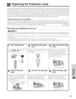
Sharp XG-P10XU XGP10XU Operation Manual - Page 52
Connection Pin Assignments
 |
View all Sharp XG-P10XU manuals
Add to My Manuals
Save this manual to your list of manuals |
Page 52 highlights
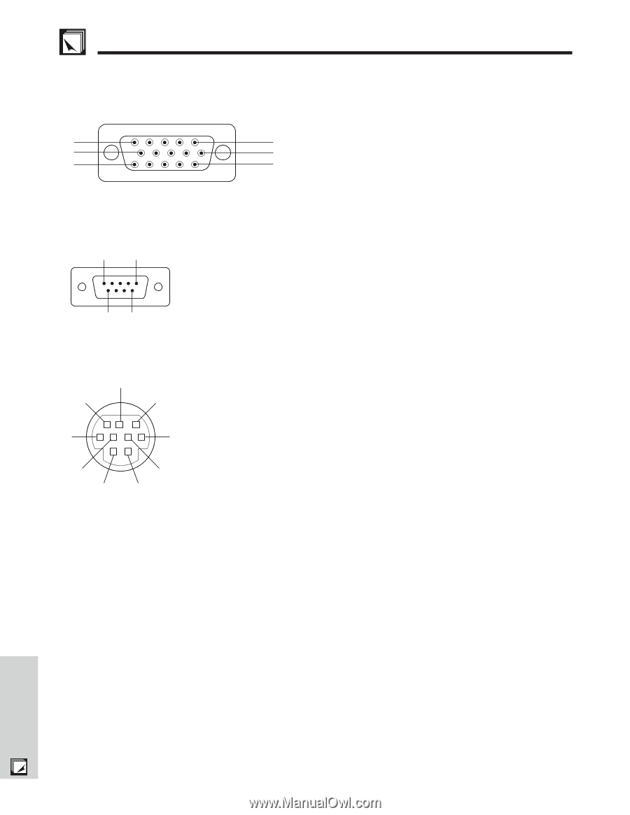
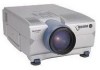
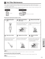
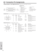
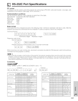
Connection Pin Assignments Analog Computer 1 and 2 Signal Input Ports: 15-pin mini D-sub female connector Computer Input Analog 1. Video input (red) 9. Not connected 2. Video input 10. GND (green/sync on green) 11. GND 5 1 3. Video input (blue) 12. Bi-directional data 10 6 4. Reserve input 1 13. Horizontal sync signal 15 11 5. Composite sync 14. Vertical sync signal 6. Earth (red) 15. Data clock 7. Earth (green/sync on green) 8. Earth (blue) RS-232C Port: 9-pin D-sub male connector of the DIN-D-sub RS-232C cable 15 69 Pin No. 1 2 3 4 5 6 7 8 9 Signal CD RD SD ER SG DR RS CS CI Name Receive Data Send Data Signal Ground Data Set Ready Request to Send Clear to Send I/O Input Output Output Output Input Reference Not connected Connected to internal circuit Connected to internal circuit Not connected Connected to internal circuit Not connected Connected to internal circuit Connected to internal circuit Not connected RS-232C Terminal: 9-pin Mini DIN connector 9 6 5 8 2 1 7 3 4 Pin No. 1 2 3 4 Signal VCC RD SD EXIR 5 SG 6 ERX 7 RS 8 CS 9 ETX Name I/O ם3.3V (Reserved) Output Receive Data Input Send Data Output Detector of Option Unit Input (Reserved) Signal Ground IR Receive Signal from Input IR Amplifier (Reserved) Request to Send Output Clear to Send Input IR Transmit Signal Output (Reserved) Reference Not connected Connected to internal circuit Connected to internal circuit Not connected Connected to internal circuit Not connected Connected to internal circuit Connected to internal circuit Not connected Appendix E-51
-
 1
1 -
2
-
3
-
4
-
5
-
6
-
7
-
8
-
9
-
10
-
11
-
12
-
13
-
14
-
15
-
16
-
17
-
18
-
19
-
20
-
21
-
22
-
23
-
24
-
25
-
26
-
27
-
28
-
29
-
30
-
31
-
32
-
33
-
34
-
35
-
36
-
37
-
38
-
39
-
40
-
41
-
42
-
43
-
44
-
45
-
46
-
 47
47 -
 48
48 -
 49
49 -
 50
50 -
 51
51 -
 52
52 -
 53
53 -
 54
54 -
 55
55 -
 56
56 -
 57
57 -
58
-
59
-
60
-
61
-
62
-
63
-
64
-
65
 |
 |