Sharp XG-P25X XG-P25X Operation Manual - Page 70
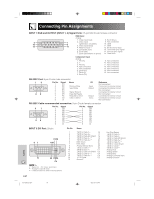
Connecting Pin Assignments
 |
View all Sharp XG-P25X manuals
Add to My Manuals
Save this manual to your list of manuals |
Page 70 highlights
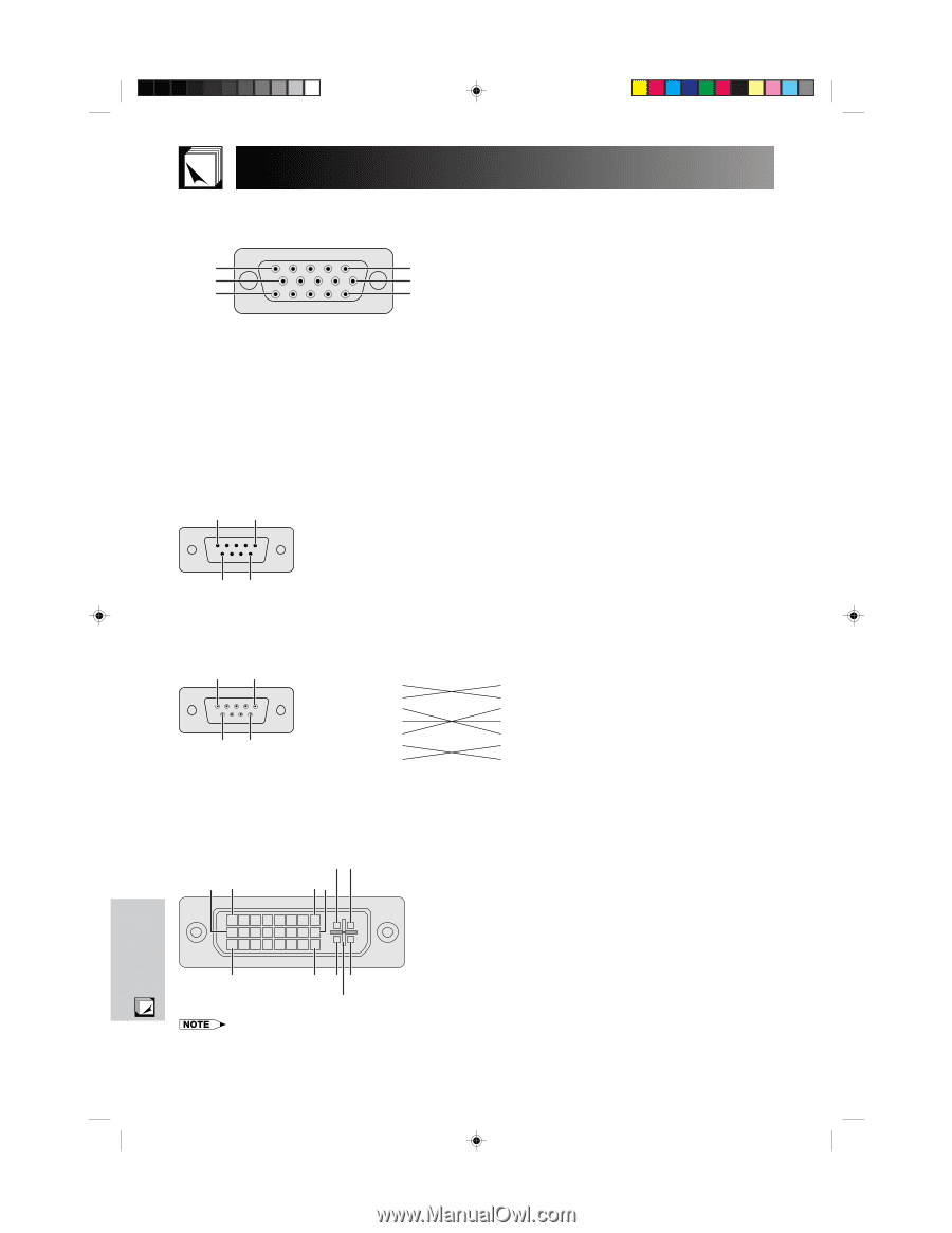
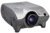
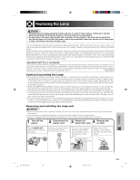
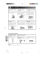
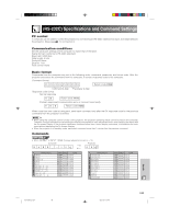
Connecting Pin Assignments INPUT 1 RGB and OUTPUT (INPUT 1, 2) Signal Ports: 15-pin Mini D-sub female connector RGB Input Analog 1. Video input (red) 8. Earth (blue) 5 10 15 1 6 11 2. Video input (green/sync on green) 3. Video input (blue) 4. Reserve input 1 9. Not connected 10. GND 11. GND 12. Bi-directional data 5. Composite sync 13. Horizontal sync signal 6. Earth (red) 14. Vertical sync signal 7. Earth (green/sync on green) 15. Data clock Component Input Analog 1. PR (CR) 2. Y 3. PB (CB) 4. Not connected 5. Not connected 6. Earth (PR) 7. Earth (Y) 8. Earth (PB) 9. Not connected 10. Not connected 11. Not connected 12. Not connected 13. Not connected 14. Not connected 15. Not connected RS-232C Port: 9-pin D-sub male connector 1 5 69 Pin No. 1 2 3 4 5 6 7 8 9 Signal CD RD SD ER SG DR RS CS CI Name Receive Data Send Data Signal Ground Data Set Ready Request to Send Clear to Send I/O Input Output Output Input Reference Not connected Connected to internal circuit Connected to internal circuit Not connected Connected to internal circuit Not connected Connected to internal circuit Connected to internal circuit Not connected RS-232C Cable recommended connection: 9-pin D-sub female connector 5 1 96 Pin No. 1 2 3 4 5 6 7 8 9 Signal CD RD SD ER SG DR RS CS CI Pin No. 1 2 3 4 5 6 7 8 9 Signal CD RD SD ER SG DR RS CS CI INPUT 3 DVI Port: 29-pin 91 C1C2 8 16 17 24 C3 C4 C5 Pin No. 1 2 3 4 5 6 7 8 9 10 11 12 13 14 15 Name T.M.D.S. Data 2 16 T.M.D.S. Data 2ם 17 T.M.D.S. Data 2/4 Shield 18 T.M.D.S. Data 4*3 19 T.M.D.S. Data 4*ם3 20 DDC Clock 21 DDC Data 22 Analog Vertical Sync 23 T.M.D.S. Data 1 24 T.M.D.S. Data 1ם C1 T.M.D.S. Data 1/3 Shield C2 T.M.D.S. Data 3*3 C3 T.M.D.S. Data 3*ם3 C4 ם5 V Power C5 Ground*1 Hot Plug Detect T.M.D.S. Data 0 T.M.D.S. Data 0ם T.M.D.S. Data 0/5 Shield T.M.D.S. Data 5*3 T.M.D.S. Data 5*ם3 T.M.D.S. Clock Shield T.M.D.S. Clockם T.M.D.S. Clock Analog Red Analog Green Analog Blue Analog Horizontal sync Analog Ground*2 • *1 Return for ם5 V, Hsync. and Vsync. • *2 Analog R, G and B return • *3 These pins are not used on this equipment. E-67 Appendix XG-P25X/CD (E)-h 67 02.3.19, 7:13 PM
-
 1
1 -
2
-
3
-
4
-
5
-
6
-
7
-
8
-
9
-
10
-
11
-
12
-
13
-
14
-
15
-
16
-
17
-
18
-
19
-
20
-
21
-
22
-
23
-
24
-
25
-
26
-
27
-
28
-
29
-
30
-
31
-
32
-
33
-
34
-
35
-
36
-
37
-
38
-
39
-
40
-
41
-
42
-
43
-
44
-
45
-
46
-
47
-
48
-
49
-
50
-
51
-
52
-
53
-
54
-
55
-
56
-
57
-
58
-
59
-
60
-
61
-
62
-
63
-
64
-
 65
65 -
 66
66 -
 67
67 -
 68
68 -
 69
69 -
 70
70 -
 71
71 -
 72
72 -
 73
73 -
 74
74 -
 75
75 -
76
-
77
-
78
-
79
-
80
 |
 |