Sharp XL-UH260 Service Manual
Sharp XL-UH260 Manual
 |
View all Sharp XL-UH260 manuals
Add to My Manuals
Save this manual to your list of manuals |
Sharp XL-UH260 manual content summary:
- Sharp XL-UH260 | Service Manual - Page 1
XL-UH260 SERVICE MANUAL No. S2603XLUH260/ MICRO COMPONENT SYSTEM MODEL XL-UH260 XL-UH260 Micro Component System consisting of XL-UH260 (main unit) and CP-UH260 (speaker system PWB/SCHEMATIC DIAGRAM 6-2 CHAPTER 7. FLOWCHART [1] TROUBLESHOOTING 7-1 CHAPTER 3. MECHANICAL DESCRIPTION [1] REMOVING AND - Sharp XL-UH260 | Service Manual - Page 2
XL-UH260 PRECAUTIONS FOR USING LEAD-FREE SOLDER 1. Employing lead-free solder "MAIN, POWER, -free solder. The LF symbol indicates lead-free solder, and is attached on the PWB and service manuals.The alphabetical character following LF shows the type of lead-free solder. Example: Indicates lead-free - Sharp XL-UH260 | Service Manual - Page 3
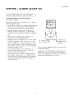
CHAPTER 1. GENERAL DESCRIPTION XL-UH260 FOR A COMPLETE DESCRIPTION OF THE OPERATION OF THIS UNIT, PLEASE REFER TO THE OPERATION MANUAL. BEFORE RETURNING THE AUDIO PRODUCT (Fire & Shock Hazard) Before returning the audio product to the user, perform the following safety checks. 1. Inspect all - Sharp XL-UH260 | Service Manual - Page 4
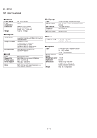
XL-UH260 [2] SPECIFICATIONS audio signal): 200 mV/10 k ohms at 70 Hz Video/Auxiliary (audio signal): 500 mV/47 k ohms USB Class Support File Format support Bitrate support Other Mass storage class MP3/WMA (do not support Weight 2-way type light-up speaker system 2" (5 cm) tweeter 5-1/8" (13 - Sharp XL-UH260 | Service Manual - Page 5
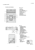
[3] NAMES OF PARTS Controls and indicators XL-UH260 Front panel 1. Disc Trays 2. Timer Indicator 3. Remote Sensor 4. Disc or USB Stop Button 6. Video/Auxiliary (Audio Signal) Input Jacks 7. Cooling Fan 8. Speaker Light-up Jacks 9. Subwoofer Pre-output Jack Speaker system 1.Tweeter 2.Woofer 3. - Sharp XL-UH260 | Service Manual - Page 6
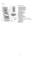
XL-UH260 1 2 3 4 5 6 11 15 7 12 16 8 13 17 9 14 18 10 19 20 21 22 23 24 25 Remote control 1. Remote Control Transmitter 2. Disc Number Select Buttons 3. Disc Direct Search Buttons 4. Equalizer Mode Select Button 5. Extra Bass/Demo Button 6. Volume Up and Down Buttons 7. Power On/ - Sharp XL-UH260 | Service Manual - Page 7
CHAPTER 2. ADJUSTMENTS [1] CD SECTION 1. CD SECTION • Adjustment Since this CD system incorporates the following automatic adjustment functions, readjustment is not needed when replacing the pickup CD**' display will only be displayed when error had been detected for the 5th times. 2 - 1 XL-UH260 - Sharp XL-UH260 | Service Manual - Page 8
XL-UH260 [2] TEST MODE • Setting the test mode During stand-by mode, press STOP button while pressing down the 3 button and 4 button. Then, press the CD button to enter the test mode.\ CD TE ST Step 1 Step 2 Step 3 Step 4 Step 5 OPEN/CLOSE operation is using manual. > key input. Laser ON. - Sharp XL-UH260 | Service Manual - Page 9
or play mode. During at Step 1 , if press >, > button can be set / >> for more than 1 sec, it directly To cancel: Power OFF XL-UH260 2 - 3 - Sharp XL-UH260 | Service Manual - Page 10
XL-UH260 [3] Standard Specification of Stereo System Error Message Display Contents CD TUNER Error Contents to enter stand-by mode. 2. While pressing down the 3 button and the will be displayed as "XL-U-****" and " FW****_V**". 4 button, press the 3. Turn the VOLUME KNOB until FL will display - Sharp XL-UH260 | Service Manual - Page 11
[4] CD Changer mechanism section • All numbers in the drawing correspond to those in parts guide (CHANGER MECHANISM PARTS). 1 XL-UH260 141 140 HALF GEAR MUST BE ARRANGED AS SHOWN 2 - 5 - Sharp XL-UH260 | Service Manual - Page 12
XL-UH260 2 139 APPLY SANKOL SHS1001 BEFORE FIX FIX ITEM 139 ACCORDING TO THE PICTURE AS SHOWN ABOVE ROTATE MODE BIG GEAR UNTIL REACH AS SHOWN IN PICTURE 2 - 6 - Sharp XL-UH260 | Service Manual - Page 13
XL-UH260 3 143 APPLY GREASE SC141 112 PULL THE LEVER UNITIL REACH THE ARROW MARK 2 - 7 - Sharp XL-UH260 | Service Manual - Page 14
XL-UH260 4 FIGURE 1 152 118 FIGURE 2 142 APPLY GREASE SC141 SLOT CLAMP SWITCH ARM INSIDE BASE SLOT HALF GEAR MUST BE ARRANGED AS SHOWN 2 - 8 - Sharp XL-UH260 | Service Manual - Page 15
5 APPLY GREASE SC141 AT BOTTOM SIDE OF GEAR FOLLOW MARKING (REFER TO GRAY AREA) NO NEED TO APPLY GREASE AT BOTTOM SIDE XL-UH260 CORRECT FIGURE 1 BLACK MARK APPLY GREASE SC141 AT TOP SIDE OF GEAR FOLLOW MARKING (REFER TO GRAY AREA) 127 IF DIRECTION IS OTHER THAN DIRECTION - Sharp XL-UH260 | Service Manual - Page 16
XL-UH260 6 APPLY GREASE SC141 AT HALF GEAR AREA ROTATE CLOCKWISE UNTIL REACH HERE (MAXIMUM) 129 2 - 10 - Sharp XL-UH260 | Service Manual - Page 17
XL-UH260 7 149 150 151 2 - 11 - Sharp XL-UH260 | Service Manual - Page 18
XL-UH260 8 THE SHOWN AREA MUST FREE FROM GREASE GREASE SC141 APPLICATION LENGTH GREASE APPLICATION PORTION CORRECT INCORRECT 124 131 SHOWN HOLE MUST FACING ARROW DIRECTION 2 - 12 - Sharp XL-UH260 | Service Manual - Page 19
XL-UH260 9 138 126 125 TR-RE JOINT GEAR C APPLY GREASE SC141 AT BOTTOM SIDE ONLY APPLY GREASE SC141 ONLY AT TOP SIDE GEAR MUST BE FIXED ACCORDINGLY TO THE HOLE'S 2 - 13 - Sharp XL-UH260 | Service Manual - Page 20
XL-UH260 10 148 147 146 145 2 - 14 - Sharp XL-UH260 | Service Manual - Page 21
XL-UH260 11 121 APPLY GREASE SC141 144 130 WHEN FIXING ITEM 144 MUST FOLLOW AS SHOWN 2 - 15 - Sharp XL-UH260 | Service Manual - Page 22
XL-UH260 12 117 FIGURE 1 FIGURE 2 APPLY GREASE SC141 FIGURE 3 APPLY GREASE SC141 2 - 16 - Sharp XL-UH260 | Service Manual - Page 23
XL-UH260 13 ITEM 133 , 134 MUST APPLY GREASE SC141 ON TOP SIDE GEAR ONLY 134 GEAR 112 133 CORRECT GEAR 112 INCORRECT 132 TOP VIEW AFTER BEING ASSEMBLED IT IS INCORRECT TO FIX IT IN REVERSED DIRECTION 2 - 17 - Sharp XL-UH260 | Service Manual - Page 24
XL-UH260 14 APPLY GREASE SC141 BEFORE FIX MOVE 112 UNTIL TOUCH THE WALL B A DURING GEAR A ROTATE MUST PRESS SHOWN AREA AND LEVER B WILL MOVE ARROW DIRECTION THEN FIX PART 108 108 803 x6 SCREW TORQUE 2 +0.5 -0 kgf-cm APPLY GREASE SC141 CONFIRM WHETHER FIXED PROPELY OR NOT 2 - 18 - Sharp XL-UH260 | Service Manual - Page 25
15 XL-UH260 APPLY GREASE SC141 113 BEHIND THE LEVER NEED TO APPLY GREASE SC141 PULL IT THEN LEVER WILL MOVE IN 2 - 19 - Sharp XL-UH260 | Service Manual - Page 26
XL-UH260 16 123 115 APPLY GREASE SC141 APPLY GREASE SC141 AT BOSS APPLY GREASE SC141 BEFORE FIX SPRING MUST BE ARRANGED UNDER THE HOOK LR JOINT LEV BOARD R BOARD R LR JOINT LEV 2 - 20 - Sharp XL-UH260 | Service Manual - Page 27
17 IT IS INCORRECT IF ASSEMBLED IN A REVERSED DIRECTION 103 137 136 APPLY GREASE SC141 XL-UH260 BIG SLOT MUST FACING OUT WHEN FIX AND AFTER FIXED TO BASE CHASSIS. AFTER ASSEMBLY, CONFIRM WITH FREE DROP TEST GEAR POSITION DURING FIXING 2 - 21 - Sharp XL-UH260 | Service Manual - Page 28
XL-UH260 18 IT IS INCORRECT IF ASSEMBLED IN A REVERSED DIRECTION APPLY GREASE SC141 104 135 136 BIG SLOT MUST FACING OUT WHEN FIX AND AFTER FIXED TO BASE CHASSIS AFTER ASSEMBLY, CONFIRM WITH FREE DROP TEST GEAR POSITION DURING FIXING CONFIRM BOTH GEARS SIT PROPERLY AND LOCKED 2 - 22 - Sharp XL-UH260 | Service Manual - Page 29
XL-UH260 19 AFTER FIX OUTER UP/DOWN LEVER HOLD AS SHOWN PORTION AND MOVE UP/DOWN THEN CONFIRM WHETHER LEVER GO INSIDE THE HOLE OR NOT - Sharp XL-UH260 | Service Manual - Page 30
XL-UH260 20 BIG SLOT FACING OUT 110 2 - 24 - Sharp XL-UH260 | Service Manual - Page 31
XL-UH260 21 PUSH THE LEVER ACCORDING TO ARROW DIRECTION THEN FIX WHEN FIXING MAIN BASE ASSEMBLY FOLLOW ACCORDING TO PICTURE 1 PICTURE 1 PICTURE 3 PICTURE 2 CORRECT INCORRECT INCORRECT MAKE SURE MECHA HOLDER SHAFT FIX PROPERLY TO LEVER 2 - 25 - Sharp XL-UH260 | Service Manual - Page 32
XL-UH260 22 APPLY SANKOL (SHS1001) APPLY SANKOL (SHS1001) ON TOP APPLY SANKOL (SHS1001) INSIDE 101 THE SLOT & OTHER SHOWN PORTION 102 APPLY SANKOL (SHS1001) APPLY SANKOL ( - Sharp XL-UH260 | Service Manual - Page 33
23 111 GEAR UP/DOWN BOARD XL-UH260 APPLY GREASE SC141 AT INNER & OUTER GEAR SLIDING PORTION WHEN FIX GEAR UP/ DOWN BOARD THE TWO LEVER MUST AT PARALLEL LINE AND POSITIONED AT TOP MAX SIDE AFTER ASSEMBLY GEAR UP/DOWN BOARD 2 - 27 - Sharp XL-UH260 | Service Manual - Page 34
XL-UH260 24 SCREW TORQUE 3 +0.5 -0 kgf-cm 804 ROTATE THE GEAR TO MOVE UP 111 GEAR UP AND DOWN BOARD BEFORE SCREW 2 - 28 - Sharp XL-UH260 | Service Manual - Page 35
25 AFTER ASSEMBLY TOP PLATE FIX THE FFC FFC4 XL-UH260 AFTER PUSH, MAKE SURE SNAP PROPERLY BACK PORTION 122 AFTER FIX, PUSH FOLLOW ARROW DIRECTION PRESS IN 107 BEFORE LOCK SLOT IN AFTER LOCK BEFORE LOCK AFTER LOCK MUST CONFIRM BEFORE LOCK AFTER LOCK MUST CONFIRM 2 - 29 - Sharp XL-UH260 | Service Manual - Page 36
XL-UH260 26 CORRECT CAUTION 1. MAKE SURE NO PWB CHIP INSIDE SET .( BEFORE FIX MAKE SURE PWB IS FREE FROM DUST , GREASE & ETC ) INCORRECT 803 2 - 30 - Sharp XL-UH260 | Service Manual - Page 37
XL-UH260 27 APPLY GREASE SC141 THE TWO SLOT MUST FREE FROM GREASE SC141 APPLY GREASE SC141 ASSEMBLY SEQUENCE BELOW THE MARKING 1. APPLY GREASE SC141 TO MAIN - Sharp XL-UH260 | Service Manual - Page 38
XL-UH260 28 13.8 + 0.2 -0 12.2 -+ 0.1 REFERENCE ONLY MOTOR GEAR HEIGHT FROM MAIN BASE 12.2 +- 0.1 MOTOR SCREWING HOLE MUST HAVE GAP M1,2 SCREW TORQUE 1.5 + 0.5 -0 AFTER SCREW MOTOR, CONFIRM THE ARRANGEMENT AS IN FIGURE 2 FIGURE 2 APPLY GREASE SC141 801 2 - 32 - Sharp XL-UH260 | Service Manual - Page 39
XL-UH260 29 APPLY SANKOL (SHS1001) 3.1 + 0.1 SHAFT X 3 DIM AFTER INSERTION MUST CONFIRM EVERYDAY SANKOL (SHS1001) APPLICATION AREA 109-2 APPLY GREASE AT THE SLIDING PORTION 114 116 UP / DOWN HOLDER CHANGE TO NATURE COLOR APPLY GREASE SC141 2 - 33 - Sharp XL-UH260 | Service Manual - Page 40
XL-UH260 30 BEFORE MELT IT AFTER MELT IT ( MUST FLAT ) WHEN FITTING STABILIZER PLATE TO STABILIZER, ROTATE STABILIZER ANTI CLOCKWISE BY JIG ( STRICTLY CANNOT FIT USING - Sharp XL-UH260 | Service Manual - Page 41
XL-UH260 31 106 APPLY GREASE SC141 MUST MAKE SURE SNAP PROPERLY BOTH SIDE ALL SURFACE MUST TOUCH GAP INCORRECT CORRECT INCORRECT 2 - 35 - Sharp XL-UH260 | Service Manual - Page 42
XL-UH260 32 NO GAP CORRECT HAVE GAP INCORRECT 2 - 36 - Sharp XL-UH260 | Service Manual - Page 43
CHAPTER 3. MECHANICAL DESCRIPTION [1] REMOVING AND REINSTALLING THE MAIN PARTS XL-UH260 1. CD MECHANISM SECTION Perform steps 1, 2, 9, 10, 11 tray so that CD can be removed from the tray. CD Disc Disc Tray Guide Tray Note After removing the connector for the optical pickup from the connector wrap - Sharp XL-UH260 | Service Manual - Page 44
XL-UH260 Reduction gear D Up Down Figure 4 Gear up down board Mark 1 Mark 3 Mark 5 (DISC 1) (DISC 3) (DISC 5) Mark 2 Mark 4 (DISC 2) (DISC 4) Figure 5 2.2. How to Remove the tray - Sharp XL-UH260 | Service Manual - Page 45
[2] DISASSEMBLY XL-UH260 Caution on disassembly Follow the below-mentioned notes when disassembling the nylon bands or wire holders where they need to be removed when disassembling the unit. After servicing the unit, be sure to rearrange the leads where they were before disassembling. 4) Take - Sharp XL-UH260 | Service Manual - Page 46
XL-UH260 Rear Panel Refresh PWB Speaker PWB (J1)x1 3x10mm (H1)x2 3x10mm CD Mechanism CD Changer Unit (P2)x4 Special Figure 4 Display PWB Front Panel ( - Sharp XL-UH260 | Service Manual - Page 47
-MEMO- XL-UH260 3 - 5 - Sharp XL-UH260 | Service Manual - Page 48
XL-UH260 CHAPTER 4. BLOCK DIAGRAM A B C D E F G H 1 2 3 4 5 6 Figure 1: CD MP3 BLOCK DIAGRAM (1/2) 4 - 1 - Sharp XL-UH260 | Service Manual - Page 49
XL-UH260 7 8 9 10 11 12 Figure 2: CD MP3 BLOCK DIAGRAM (2/2) 4 - 2 - Sharp XL-UH260 | Service Manual - Page 50
XL-UH260 A B CHASSIS_GND NC FM_DET TUN_SM R_CH +B2 +9V L_CH T U N _ S M / S PA N SP_DET D L VIDEO/AUX L DI R R CE E JK690 IC601 CLK TUNER L LC75341 R AUDIO PROCESSOR R L CNP601 L FROM 1 R CD/MP3 SECTION 2 3 4 +B2 F 8.5V +B1 +B2 10V +B3 13V 9 CNP601 8 TO - Sharp XL-UH260 | Service Manual - Page 51
XL-UH260 DI CE KEY SW707-SW712 SW704-SW706 SW701-SW703 +B8 AV C C IC702 SYSTEM MICROCOMPUTER +B8 IC705 V O LTA G E R E G U L AT O R + S P _ R LY F805 4A 125V RL841 AC RELAY XL701 Q905 +B8 REMOTE SENSOR RX701 XL702 DIMM_LED QS15 TO CD/ MP3 SECTION Q701 IC703 RESET CCT QS01 - Sharp XL-UH260 | Service Manual - Page 52
XL-UH260 CHAPTER 5. CIRCUIT DESCRIPTION [1] WAVEFORM OF SERVO CIRCUIT 1 IC3 33 2 IC3 34 1 IC3 33 6 IC3 41 1 IC3 33 6 IC3 41 4 IC3 31 1 IC3 33 9 IC5 13 10 IC5 12 11 IC5 11 1 IC3 33 5 IC3 24 4 IC3 11 7 IC3 17 8 IC3 19 6 IC3 41 1 IC3 33 5 IC3 24 5 - 1 - Sharp XL-UH260 | Service Manual - Page 53
12 IC6 34 13 IC6 49 14 IC6 38 IC6 39 15 18 IC6 8 19 IC6 9 20 IC6 21 16 IC6 57 17 IC6 56 XL-UH260 5 - 2 - Sharp XL-UH260 | Service Manual - Page 54
XL-UH260 [2] IC VOLTAGE IC 702 PIN NO VOLTAGE PIN VOLTAGE NO 1 0 51 3.272v 2 0 52 3.106v 3 0 53 3.269v 4 0 54 3.268v 5 0 55 3.106v 6 0 56 3.202v 7 0 57 3.202v 8 0 58 3. - Sharp XL-UH260 | Service Manual - Page 55
Q1 No. 1 2 3 Q3 No. 1 2 3 Q5 No. 1 2 3 Q9 No. 1 2 3 Q11 No. 1 2 3 Voltage 1.5 2.6 3.2 Voltage 2 0 0 Voltage 5 5 4.3 Voltage 3.3 2.7 3.3 Voltage 5.1 4.4 5.1 5 - 4 XL-UH260 Q2 No. 1 2 3 Q4 No. 1 2 3 Q7 No. 1 2 3 Q10 No. 1 2 3 Q12 No. 1 2 3 Voltage 5 3.2 4.3 Voltage 0 3.2 0 Voltage 0 3 0 Voltage - Sharp XL-UH260 | Service Manual - Page 56
XL-UH260 C) IC 4 (MP3 WMA Decoder) No. Voltage 1 1.5 2 3.2 3 0 4 0 5 0 6 3.2 7 0 8 3.3 9 3.3 10 0 11 0 12 1.8 13 1.7 14 0 15 1.7 16 1.6 17 2.4 18 3 19 2.4 20 1.7 21 1.5 22 0 23 0 24 0 25 0 26 0 27 0 28 0 - Sharp XL-UH260 | Service Manual - Page 57
XL-UH260 CHAPTER 6. CIRCUIT SCHEMATICS AND PARTS LAYOUT [1] Notes on schematic diagram • Resistor: To differentiate the units of resistors, such symbol as K and M are used: the symbol K - Sharp XL-UH260 | Service Manual - Page 58
XL-UH260 A B C D E F FM SIGNAL G H 1 2 3 4 5 6 Figure 6-1: POWER SCHEMATIC (1/2) 6 - 2 - Sharp XL-UH260 | Service Manual - Page 59
XL-UH260 7 8 9 10 11 12 Figure 6-1: POWER SCHEMATIC (2/2) 6 - 3 - Sharp XL-UH260 | Service Manual - Page 60
XL-UH260 A B CD SIGNAL AUX SIGNAL C694 1/50V C693 1/50V C D E F G NC NC NC NC H 1 2 3 4 5 6 Figure 6-2: MAIN SCHEMATIC (1/2) 6 - 4 - Sharp XL-UH260 | Service Manual - Page 61
XL-UH260 FOR FLASH USB MICOM IC ONLY REFLASH MICOM PWB-A4 CNPU1 CWYH30AWZZ NC 30 A6 29 A4 28 A0 27 I/0 26 A2 25 I/03 24 - Sharp XL-UH260 | Service Manual - Page 62
XL-UH260 A LUG 2 LUG 3 B JACK PWB TO MAIN SECTION C D E F G H 1 2 3 4 5 6 Figure 6-3: DISPLAY SCHEMATIC (1/2) 6 - 6 - Sharp XL-UH260 | Service Manual - Page 63
XL-UH260 7 8 9 10 11 12 Figure 6-3: DISPLAY SCHEMATIC (2/2) 6 - 7 - Sharp XL-UH260 | Service Manual - Page 64
XL-UH260 A B CD SIGNAL C D E CD MOTOR PWB-E 4 4 3 3 2 2 1 1 F TRAY CHANGER MOTOR PWB-F G H 1 2 3 4 5 6 Figure 6-4: CD MP3 SCHEMATIC (1/2) 6 - 8 - Sharp XL-UH260 | Service Manual - Page 65
XL-UH260 TO REFRESH PWB CNPU1 270P CNP6 WYP30AW 1mm Pitch 7 8 9 10 11 12 Figure 6-4: CD MP3 SCHEMATIC (2/2) 6 - 9 - Sharp XL-UH260 | Service Manual - Page 66
XL-UH260 SPEAKER PWB-A3 A B C FROM MAIN PWB-A1 - - SO901 SPEAKER TERMINAL + + RIGHT LEFT COLOR is used in the MAIN,SPEAKER PWB. Refer to "Precautions for handling lead-free solder" for instructions and precautions. 2 3 4 5 6 Figure 6-5: WIRING SIDE OF MAIN PWB (TOP VIEW) (1/2) 6 - 10 - Sharp XL-UH260 | Service Manual - Page 67
XL-UH260 ANTENNA TUNER PACK FM GND AM 2 4 6 8 10 1 3 5 7 9 11 TO TUNER PACK 1 2 3 4 solder is used in the REFLASH MICOM PWB Refer to "Precautions for handling lead-free solder" for instructions and precautions. JK690 VIDEO/AUX IN CHASSIS GND LEFT RIGHT M971(202-3) FANMOTOR REDMARK BK 2 BR - Sharp XL-UH260 | Service Manual - Page 68
XL-UH260 A B C POWER PW B -A2 PT841 SUB POWER TRANSFORMER 4 5 3 6 1 7 8 2 9 1 PT801 MAIN POWER TRANSFORMER 1 2 3 4 5 6 7 AC to "Precautions for handling lead-free solder" for instructions and precautions. 1 2 3 4 5 6 Figure 6-6: WIRING SIDE OF POWER PWB (TOP VIEW) 6 - 12 - Sharp XL-UH260 | Service Manual - Page 69
-MEMO- XL-UH260 6 - 13 - Sharp XL-UH260 | Service Manual - Page 70
XL-UH260 A MAIN PWB-A1 B C D 18 17 16 15 14 13 12 11 10 9 8 7 6 5 4 3 2 1 E F G H 1 2 3 4 5 6 Figure 6-7: WIRING SIDE OF MAIN PWB (BOTTOM VIEW) (1/2) 6 - 14 - Sharp XL-UH260 | Service Manual - Page 71
XL-UH260 Lead-free solder indication Lead-free solder is used in the MAIN PWB. Refer to "Precautions for handling lead-free solder" for instructions and precautions. 7 8 9 10 11 12 Figure 6-7: WIRING SIDE OF MAIN PWB (BOTTOM VIEW) (2/2) 6 - 15 - Sharp XL-UH260 | Service Manual - Page 72
XL-UH260 A B C 321 D 123 E F 123 2 4 6 8 10 12 14 16 1 3 5 7 9 11 13 15 G 1 16 Lead-free solder indication Lead-free solder is used in the DISPLAY PWB. CNP701B H Refer to "Precautions for handling lead-free solder" for instructions and precautions. TO MAIN PWB-A1 1 2 3 4 5 - Sharp XL-UH260 | Service Manual - Page 73
COLOR RD WH YL GR TABLE RED WHITE YELLOW GREEN XL-UH260 231 8 10 12 14 16 18 20 7 9 11 13 15 17 19 2 4 6 8 10 1 3 5 7 9 11 1 7 RD GR YL GR YL GR 20 CNP5 D SERVO PWB 7 1 11 - Sharp XL-UH260 | Service Manual - Page 74
XL-UH260 BI2 FROM CD MP3 PWB A COLOR TABLE BK BLACK GY GRAY WH WHITE B C 1 23 4 WH JK702 USB JACK is used in the USB, SUB, JACK, LED PWB. Refer to "Precautions for handling lead-free solder" for instructions and precautions. 2 3 4 5 6 Figure 6-8: WIRING SIDE OF PWB (TOP VIEW) (3/3) 6 - 18 - Sharp XL-UH260 | Service Manual - Page 75
-MEMO- XL-UH260 6 - 19 - Sharp XL-UH260 | Service Manual - Page 76
XL-UH260 A B DISPLAY PWB-B1 1 2 3 4 5 6 7 8 9 10 11 12 13 14 15 16 17 18 19 2021 22 23 24 25 26 27 28 29 30 C D E F G Lead-free solder indication Lead-free solder is used in the DISPLAY PWB. Refer to "Precautions for handling lead-free solder" for instructions H and precautions. 1 2 3 - Sharp XL-UH260 | Service Manual - Page 77
6 27 28 29 30 31 32 33 34 35 36 37 38 39 40 41 42 43 44 45 46 47 48 49 50 51 XL-UH260 7 8 9 10 11 12 Figure 6-9: WIRING SIDE OF DISPLAY PWB (BOTTOM VIEW) (2/3) 6 - 21 - Sharp XL-UH260 | Service Manual - Page 78
XL-UH260 A B C748 C751 C D SUB PWB-B5 USB PWB-B2 E F JACK PWB-B3 G H 1 LED PWB-B4 Lead-free solder indication Lead-free solder is used in the USB, JACK, LED PWB. Refer to "Precautions for handling lead-free solder" for instructions and precautions. 2 3 4 5 6 Figure 6-9: WIRING SIDE - Sharp XL-UH260 | Service Manual - Page 79
-MEMO- XL-UH260 6 - 23 - Sharp XL-UH260 | Service Manual - Page 80
XL-UH260 A B C CD MP3 PWB-C COLOR TABLE BR BROWN RD(R) RED BK BLACK 17 19 Lead-free solder is used in the CD MP3 PWB. Refer to "Precautions for handling lead-free solder" for instructions 1 and precautions. FFC702 H 1 2 3 4 5 Figure 6-10: WIRING SIDE OF CD MP3 PWB (1/2) 6 - 24 20 - Sharp XL-UH260 | Service Manual - Page 81
FFCI 1 1 2 WH GR WH RD TO CD MOTOR PWB-E CNP2A 3456 1 2 3 4 1234 E CB C12 R13 11 9 7 5 3 1 10 8 6 4 2 CNP3 1 FFC3 CNP1 TO CD CHANGER PWB-F XL-UH260 11 30 CNPU1 TREFLASH MICOMO PWB-A4 2 4 6 8 10 12 14 16 18 20 22 24 26 28 30 1 3 5 7 9 11 13 15 17 19 21 23 - Sharp XL-UH260 | Service Manual - Page 82
XL-UH260 A B CD MP3 PWB-C C D E F G Lead-free solder indication H Lead-free solder is used in the CD MP3 PWB. Refer to "Precautions for handling lead-free solder" for instructions and precautions. 1 2 3 4 5 6 Figure 6-11: CD MP3 PWB (BOTTOM VIEW) 6 - 26 - Sharp XL-UH260 | Service Manual - Page 83
XL-UH260 CD PICK-UP A CNP2A M2A SLED MOTOR B 3 456 CD MOTOR PWB-E 1 3 5 7 9 11 13 15 2 4 is used in the CD CHANGER, CD MOTOR PWB. Refer to "Precautions for handling lead-free solder" for instructions and precautions. The numbers 1 to 20 are waveform numbers shown in page 5-1 & 5-2 1 2 3 - Sharp XL-UH260 | Service Manual - Page 84
XL-UH260 CHAPTER 7. FLOWCHART [1] TROUBLESHOOTING , check the following items. Remove the cabinet and follow the trouble shooting instructions. "Track skipping and/or no TOC (Table Of Contents) Focus-RF system check 2) Tracking system check 3) Spin system check 4) PLL system check 5) Others 7 - 1 - Sharp XL-UH260 | Service Manual - Page 85
XL-UH260 3. When the USB does not function. 3.1. "NO MEDIA" is displayed. 1) Check the power to IC6 (OTI6888QFP), IC7 (RHIXA093AW00) and BI2 connector. 2) Check the system microcomputer (especially the communication line with the USB Host). 3) Check the grounding condition to IC6 (OTI6888QFP), IC7 - Sharp XL-UH260 | Service Manual - Page 86
XL-UH260 (2) Focus-RF system check. Check the TE waveform at pin 31 on IC3. If the IC1. Data cannot be read. Check the VCO-PLL (Pins 16~19 and 21 on IC3) system. 4 IC3 31 1 IC3 33 (3) Spin system check. Press the OPEN/CLOSE switch without inserting a disc, and then try starting the play operation - Sharp XL-UH260 | Service Manual - Page 87
(4) PLL system check. When a disc is loaded, start play operation. The RF waveform is normal, but the TOC data cannot be read. Check the IMAX waveform. (Figure 6) Check around Pins 16~19, and 21 on IC3. 7 IC3 17 8 IC3 19 6 IC3 41 1 IC3 33 Figure 6 XL-UH260 (5) Others. The RF waveform is normal - Sharp XL-UH260 | Service Manual - Page 88
XL-UH260 (6) USB system check. Press USB funnction, insert the USB memory device into the USB. 1. Does the device information can display? Yes 2. The waveform and the time is - Sharp XL-UH260 | Service Manual - Page 89
pin (-) for tracking coil. In this unit, the terminal with asterisk mark (*) is (open) terminal which is not connected to the outside. * Set power system GND to the minimum potential together with SGND * Short-circuit three pins of power system SVSS and PVCC1 externally before use. XL-UH260 8 - 1 - Sharp XL-UH260 | Service Manual - Page 90
- + + - + + - IC2 VHILA6261//-1: Focus/Tracking/Spin/Sled Driver (LA6261) 1 CH3 2 3 4 5 CH2 6 7 8 9 CH1 Pre Drive Pre Drive XL-UH260 + - 36 CH4 35 + - 34 33 32 CH5 31 30 29 28 CH6 VOLTAGE CONTROL AMP + 10 22k 11 11k + 12 1k 22k 13 11k + 14 - Sharp XL-UH260 | Service Manual - Page 91
connection pin. Treble band filter comprising capacitor and resistor connection pin. Volume + equaliser output pin. Input selector output pin. IC601 VHiLC75341/-1: Audio Processor (LC75341) XL-UH260 Pin No. Terminal Name Function 9-12 L4-1 Input signal pin. Pin No. 13-16 17 18 19 20 21 22 23 - Sharp XL-UH260 | Service Manual - Page 92
Input/Outputs Write Enable Chip Enable Output Enable Supply Voltage Ground Table 1 PIN DESCRIPTION A0-A15 EN29LV512 DQ0-DQ7 CE# OE# WE# Figure 4 LOGIC DIAGRAM XL-UH260 8 - 4 - Sharp XL-UH260 | Service Manual - Page 93
Enable Output Enable Logic DQ0-DQ7 Input/Output Buffers STB Data Latch Vcc Detector A0-A15 Address Latch Timer Y-Decoder STB X-Decoder Y-Gating Cell Matrix XL-UH260 Figure 5 BLOCK DIAGRAM OF IC 8 - 5 - Sharp XL-UH260 | Service Manual - Page 94
pF 60 kΩ 60 kΩ 1 kΩ 14 kΩ 2 kΩ 7 LDO 6 MDI 1.75 kΩ k x0.5 x2 5 TNI 1 x0.5 x2 94 kΩ 22 kΩ 4 TPI 3 FPI 94 kΩ 22 kΩ 2 FNI 1 Vcc Figure 6 BLOCK DIAGRAM OF IC XL-UH260 PIN VCTRL VCC HIZ GND SEL (APC SW) APC ON APC ON APC OFF (LDO=H) TEB (TE BAL) -50% 0% +50% RFGC (AGC Gain) +12dB +6dB - Sharp XL-UH260 | Service Manual - Page 95
IC6 VHIOTI6888QFP: USB DRIVER BLOCK DIAGRAM 14.318MHz XL-UH260 Input Button PLL RISC Program RAM Clock Divider UHC Interrupt LED USB Transceirver D+ USB D- device 12V Bit Stream DAC MP3 Decoder LED1~2 Figure 7 BLOCK DIAGRAM OF IC 8 - 7 - Sharp XL-UH260 | Service Manual - Page 96
XL-UH260 IC701 VHIM66005AF-1:FL DRIVER PIN CONFIGURATION DIG11 1 DIG10 2 DIG09 3 DIG08 4 DIG07 5 Digit DIG06 6 outputs DIG05 7 DIG04 8 DIG03 9 DIG02 10 DIG01 11 DIG00 12 Reset input - Sharp XL-UH260 | Service Manual - Page 97
Drive + - Prc Drive + - Prc Drive 5 MODE 1 Referenc e Voltag e 23 R EG 3 VC C 13V 4 G ND 1 REG4 5.1V 7 REG1 8.5V Figure 10 BLOCK DIAGRAM OF IC 6 REG2 10.0 V XL-UH260 8 - 9 - Sharp XL-UH260 | Service Manual - Page 98
XL-UH260 [2] FL DISPLAY FL701 VVKNA12MM54-1 GRID ASSIGNMENT 1G 12G 1a 2a 1a 2a 1a 2a 1a 2a 1a 2a MP3 WMA 1a 1a 1a 2a 2a - Sharp XL-UH260 | Service Manual - Page 99
GUIDE XL-UH260 MICRO COMPONENT SYSTEM MODEL XL-UH260 XL-UH260 Micro Component System consisting of XL-UH260 (main unit) and CP-UH260 (speaker system ] ACCESSORIES [15] P.W.B. ASSEMBLY (Not Replacement Item) [16] OTHER SERVICE PARTS Parts marked with " " are important for maintaining the safety of - Sharp XL-UH260 | Service Manual - Page 100
XL-UH260 NO. PARTS CODE [1] INTEGRATED CIRCUITS IC1 IC2 IC3 IC4 IC5 IC6 TYPE ) AE CMOS IC ( 1.5V ) AE CMOS IC ( 3.3V ) AM Audio Processor,LC75341 AR Sound IC (24 Pin) AT FL DRIVER BD SYSTEM MICOM AG Reset,PST9127 AF REGULATOR 3.3V AF REGULATOR 3.3V AL MULTI REGULATOR IC AF - Sharp XL-UH260 | Service Manual - Page 101
AA 0.022 µF,16V AC 220 µF,10V,Electrolytic AB 100 µF,10V,Electrolytic AB 0.1 µF,16V AC 10 µF,50V,Electrolytic AA 0.022 µF,16V AB 1000 µF,6.3V,Electrolytic 2 DESCRIPTION XL-UH260 - Sharp XL-UH260 | Service Manual - Page 102
XL-UH260 NO. PARTS CODE [7] CAPACITORS C15 VCKYCY1HB103K C16 VCKYCY1CB104K C17 VCKYCY1CB104K C18 VCKYCY1HB682K C19 VCKYCY1CB104K C20 VCKYCY1CB104K C21 VCCCCY1HH1R0C C22 VCEAZA1AW107M C23 VCKYCY1CB104K C24 VCEAZA1AW107M C25 - Sharp XL-UH260 | Service Manual - Page 103
AA 10 p F (CH),50V AA 10 p F (CH),50V AA 0.001 µF,50V AA 270 p F (CH),50V AB 10 µF,16V,Electrolytic AA 0.1 µF,25V AB 1 µF,50V,Electrolytic 4 DESCRIPTION XL-UH260 - Sharp XL-UH260 | Service Manual - Page 104
XL-UH260 NO. PARTS CODE [7] CAPACITORS C737 RC-EZD105AF1H C738 VCKYCY1EF104Z C739 VCKYCY1HB222K C740 VCKYCY1HB222K C742 VCKYCY1HB222K C743 RC-EZD107AF1A C746 VCKYCY1HB103K C748 VCCCCY1HH470J C751 VCCCCY1HH470J C754- - Sharp XL-UH260 | Service Manual - Page 105
AA 1 kohms,1/4W AA 2.7 kohms,1/16W AB 0 ohms,Jumper AA 2.7 kohms,1/16W AA 100 ohms,1/16W AA 1 Mohms,1/16W AA 0 ohms,Jumper,0.8x1.55mm,Green 6 XL-UH260 - Sharp XL-UH260 | Service Manual - Page 106
XL-UH260 NO. PARTS CODE [8] RESISTORS R50 R51 R52 R53 R55 R56 R58 R59 R60 R61 R63 R64 R65 R66 R67 R68 R69 R70 R71 R72 R73 - Sharp XL-UH260 | Service Manual - Page 107
,1/16W AA 1 kohms,1/16W AA 1 kohms,1/16W AA 1 kohms,1/6W AA 1 kohms,1/6W AA 1 kohms,1/6W AA 1 kohms,1/6W AA 1 kohms,1/16W AA 1 kohms,1/16W 8 XL-UH260 - Sharp XL-UH260 | Service Manual - Page 108
XL-UH260 NO. PARTS CODE [8] RESISTORS R787 VRS-CY1JB102J R788 VRD-ST2CD102J R789 VRD-ST2CD102J R790 VRD-ST2CD102J R791 VRD-ST2CD102J R792 VRD-ST2CD102J R793 VRD-ST2CD102J - Sharp XL-UH260 | Service Manual - Page 109
Socket,11Pin Socket,11Pin Socket,20Pin Socket,30Pin Socket,11Pin FFC Cable,11 Pin Plug,9Pin Socket,20Pin Plug,2Pin Socket,11Pin Plug,4Pin 10 XL-UH260 - Sharp XL-UH260 | Service Manual - Page 110
XL-UH260 NO. PARTS CODE PRICE NEW PART RANK MARK RANK DESCRIPTION Flat Wire,5 Pin Jack,Video/AUX Jack,Headphones Jack,USB Sub Woofer Output Lug Lug Lug Lug Relay,Power Relay,Speaker Remote Sensor,2013TH2E1 Terminal,Speaker Switch,Key Type [ DISC 4 ] Switch,Key Type [ DISC 5 ] Switch,Key Type - Sharp XL-UH260 | Service Manual - Page 111
-MEMO- XL-UH260 12 - Sharp XL-UH260 | Service Manual - Page 112
XL-UH260 [10] CD MECHANISM PARTS A 306-2 306 306-1 306-3 701 704 B 701 304 C 302 301 D 703x2 E M1A F 305x2 G 307 308 M2A H PWB-E 1 2 3 4 5 6 13 - Sharp XL-UH260 | Service Manual - Page 113
M1A 92LMTR6447CASY AQ M2A 92LMTR6447BASY AN Gear,Middle Gear,Drive Shaft,Guide Cushion Pickup Unit Ass'y Pickup Unit (Not Replacement Item) Gear,Rack Spring,Rack Cushion Cushion Screw,M2.6x6mm Screw,M2x3mm Washer,M1.5xM3.8x0.25mm Motor with Chassis [Spindle] Motor with Gear [Sled] XL-UH260 14 - Sharp XL-UH260 | Service Manual - Page 114
XL-UH260 [] [11] CHANGER MECHANISM PARTS 122 A 101x2 107 B 102x5 C D E F G H 1 101x3 115 109-3 116 109 109-2 123 803x4 109-5 109-4 803x2 109-1 114 108 135 104 106 - Sharp XL-UH260 | Service Manual - Page 115
SW2 QSW-P9003AWZZ AD SW3 QSW-P9003AWZZ AD SW4 QSW-P9006AWZZ AF Disc Tray Guide Tray Outer Tray Guide Inner Tray Guide Main Base CD Mechanism Holder Top Plate Gear Plate Up/Down Holder Ass'y Stabilizer ,Push Type [TRAY SW1] Switch,Push Type [TRAY SW2] Switch,Push Type [DISC] XL-UH260 16 - Sharp XL-UH260 | Service Manual - Page 116
XL-UH260 [] [12] CABINET PARTS A CD CHANGER MECHANISM UNIT 205 609x2 609X2 225 206x5 B 217 208 613x2 609x2 613x2 209 608x2 608x2 C 613x2 216 PWB-C 216 613x2 - Sharp XL-UH260 | Service Manual - Page 117
AM Panel, FL Display AD Badge, SHARP AE Button, Function, A AE Button, , Right AM Knob, VOLUME AC Bracket, PWB Support AA Nylon Band AD Bushing, AC Power Supply Power Supply Cord AC Lug (LG2-5) AR Label, Specification - Nut (Not Replacement Item ) - Washer (Not XL-UH260 18 - Sharp XL-UH260 | Service Manual - Page 118
XL-UH260 [] [13] SPEAKER BOX PARTS 902 A 907x2 B C 906x2 D SP3,4 905x4 E TWEETER SP3(L-CH) SP4(R-CH) - + SP1,2 BK RED RED C1,2 + Capacitor F solder is used in the SPEAKER LED PWB. Refer to "Precautions for handling lead-free solder" for instructions and precautions. 4 5 6 19 - Sharp XL-UH260 | Service Manual - Page 119
XEBY730P10000 RSP-ZA182AWZZ RSP-ZA183AWZZ XESY730P10000 PRICE NEW PART RANK MARK RANK AL Wooden Box Ass'y AW Front Panel Ass'y AB Cushion, Foot AD Label, Specification AB Screw, M4 X16mm AA Screw, M3 X10mm AM Woofer AL Tweeter AA Screw, M3X10mm DESCRIPTION XL-UH260 20 - Sharp XL-UH260 | Service Manual - Page 120
XL-UH260 [] [14] ACCESSORIES UNIT PACKING METHOD Polyethylene Bag,Unit SSAKH0094AWZZ Front Speaker(L/R) A SPAKZA308AWZZ AM Loop Antenna B FM Antenna Remote Control Polyethylene Bag,Accessories SSAKAA006AWZZ Operation Manual Quick Guide B FRONT A Packing Case SPAKCA332AWZZ Front of - Sharp XL-UH260 | Service Manual - Page 121
TINSEA123AWZZ AD TINSZA183AWZZ AC 92LFANT1535A AF AM Loop Antenna Remote Control Operation Manual Quick Guide FM Antenna [15] P.W.B. ASSEMBLY ( Not Replacement Only) CD Changer Motor (PWB Only) [16] OTHER SERVICE PARTS UDSKA0004AFZZ AZ CD Optical Pickup Lens Cleaner Disc XL-UH260 22 - Sharp XL-UH260 | Service Manual - Page 122
XL-UH260 "HOW TO ORDER REPLACEMENT PARTS" To have your order filled promptly and correctly, please furnish the following information. 1. MODEL NUMBER 2. REF. No. For U.S.A. only Contact your nearest SHARP Parts Distributor to order. 3. PART NO. 4. DESCRIPTION For location of SHARP Parts - Sharp XL-UH260 | Service Manual - Page 123
-MEMO- XL-UH260 24 - Sharp XL-UH260 | Service Manual - Page 124
XL-UH260 COPYRIGHT © 2006 BY SHARP CORPORATION ALL RIGHTS RESERVED. No par t of this publication may be reproduced, stored in a retrieval system, or transmitted in any form or by any means, electronic, mechanical, photocopying , recording, or otherwise, without prior written permission of the
-
 1
1 -
 2
2 -
 3
3 -
 4
4 -
 5
5 -
 6
6 -
 7
7 -
8
-
9
-
10
-
11
-
12
-
13
-
14
-
15
-
16
-
17
-
18
-
19
-
20
-
21
-
22
-
23
-
24
-
25
-
26
-
27
-
28
-
29
-
30
-
31
-
32
-
33
-
34
-
35
-
36
-
37
-
38
-
39
-
40
-
41
-
42
-
43
-
44
-
45
-
46
-
47
-
48
-
49
-
50
-
51
-
52
-
53
-
54
-
55
-
56
-
57
-
58
-
59
-
60
-
61
-
62
-
63
-
64
-
65
-
66
-
67
-
68
-
69
-
70
-
71
-
72
-
73
-
74
-
75
-
76
-
77
-
78
-
79
-
80
-
81
-
82
-
83
-
84
-
85
-
86
-
87
-
88
-
89
-
90
-
91
-
92
-
93
-
94
-
95
-
96
-
97
-
98
-
99
-
100
-
101
-
102
-
103
-
104
-
105
-
106
-
107
-
108
-
109
-
110
-
111
-
112
-
113
-
114
-
115
-
116
-
117
-
118
-
119
-
120
-
121
-
122
-
123
-
124
 |
 |
XL-UH260
MICRO COMPONENT SYSTEM
This document has been published to be used for after
sales service only.
The contents are subject to change without notice.
XL-UH260
MODEL
• In the interests of user-safety (Required by safety regula-
tions in some countries) the set should be restored to its
original condition and only parts identical to those specified
be used.
XL-UH260 Micro Component System consisting of
XL-UH260 (main unit) and CP-UH260 (speaker system).
PRECAUTIONS FOR USING LEAD-FREE SOLDER
CHAPTER 1. GENERAL DESCRIPTION
[1]
IMPORTANT SERVICE NOTES
........... .......
1-1
[2]
SPECIFICATIONS
........................................
1-2
[3]
NAMES OF PARTS
......................................
1-3
CHAPTER 2. ADJUSTMENTS
[1]
CD Section
....................................................
2-1
[2]
TEST MODE
.................................................
2-2
[3]
Standard Specification of Stereo System
Error Message Display Contents
........... .......
2-4
[4]
CD Changer Mechanism Section
................
2-5
CHAPTER 3. MECHANICAL DESCRIPTION
[1]
REMOVING AND REINSTALLING THE MAIN
PARTS
..........................................................
3-1
[2]
DISASSEMBLY
.............................................
3-3
CHAPTER 4. DIAGRAMS
[1]
BLOCK DIAGRAM
........................................
4-1
CHAPTER 5. CIRCUIT DESCRIPTION
[1]
WAVEFORMS OF SERVO CIRCUIT
.............
5-1
[2]
VOLTAGE
................................................
......
5-3
CHAPTER 6. CIRCUIT SCHEMATICS AND PARTS
LAYOUT
[1]
NOTES ON SCHEMATIC DIAGRAM
............
6-1
[2]
TYPES OF TRANSISTOR AND LED
............
6-1
[3]
WIRING SIDE OF PWB/SCHEMATIC
DIAGRAM
......................................................
6-2
CHAPTER 7. FLOWCHART
[1]
TROUBLESHOOTING
...................................
7-1
CHAPTER 8. OTHERS
[1]
FUNCTION TABLE OF IC
.............................
8-1
[2]
FL DISPLAY
.................................................
8-10
Parts Guide
SERVICE MANUAL
No. S2603XLUH260/
CONTENTS
Parts marked with "
" are important for maintaining the safety of the set. Be sure to replace these parts with specified
ones for maintaining the safety and performance of the set.
CONTENTS