Snapper RE110 Operater's Manual - Page 27
Rear Engine Rider Drive, Components, WARNING, Maintenance, IMPORTANT
 |
View all Snapper RE110 manuals
Add to My Manuals
Save this manual to your list of manuals |
Page 27 highlights
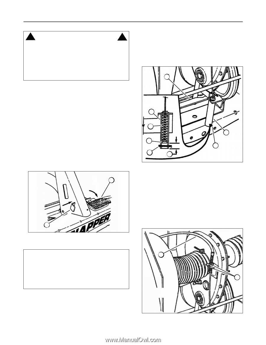
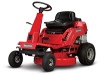
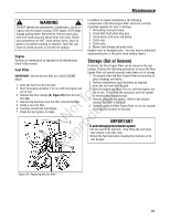
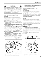
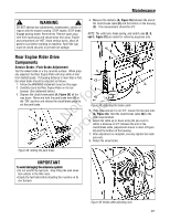
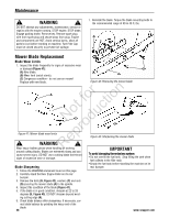
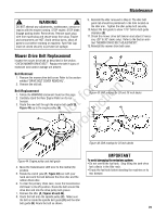
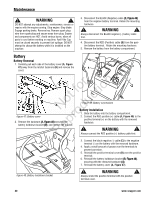
Maintenance ! WARNING ! DO NOT attempt any adjustments, maintenance, service or repairs with the engine running. STOP engine. STOP blade. Engage parking brake. Remove key. Remove spark plug wire from spark plug and secure away from plug. Engine and components are HOT. Avoid serious burns, allow all parts to cool before working on machine. Fuel Filler Cap must be closed securely to prevent fuel spillage. 4. Measure the distance (A, Figure 39) between the end of the clutch/brake cable (B) and the bottom of the housing (C). The measurement should be 3/4". NOTE: The cotter pin, brake spring, and clutch yoke (D, E, and F, Figure 39) are noted for reference purposes only. E Rear Engine Rider Drive Components Service Brake / Park Brake Adjustment Test the wheel brake on a dry concrete surface. When prop- C erly adjusted, the Rear Engine Rider will stop within 5 feet from fastest speed. If stopping distance is more than 5 feet, the wheel brake should be adjusted as follows: E 1. Follow the WARNING statement found on this page. 2. Carefully stand the Rear Engine Rider on its rear bumper. (See statement below.) r n 3. Depress the clutch/brake pedal (A, Figure 38) all the fo tio way down. Move and hold the park brake lever (B) in the "ON" position and release the clutch/brake pedal to set the park brake. ot uc A RNeprod B B D A C D Figure 39: Adjusting the brake cable 5. If the measurement is not 3/4", loosen the two jam-nuts (A, Figure 40). Hold the clutch/brake cable (B) to the chain case bracket. 6. Adjust the cable up or down using the jam-nuts to obtain a distance of 3/4" between the end of the clutch/brake cable (adjustment shown in inset of Figure 40) and the bottom of the housing. 7. After adjustment is complete, securely tighten the cable jam-nuts. 8. Retest the wheel brake. Figure 38: Setting the park brake IMPORTANT A To avoid damaging the emissions system: • Do not overfill the fuel tank. Stop filling the tank when fuel collects in the filler neck. • Empty the fuel tank before standing the machine on its B rear bumper. Figure 40: Brake cable adjusting nuts 27
-
 1
1 -
2
-
3
-
4
-
5
-
6
-
7
-
8
-
9
-
10
-
11
-
12
-
13
-
14
-
15
-
16
-
17
-
18
-
19
-
20
-
21
-
 22
22 -
 23
23 -
 24
24 -
 25
25 -
 26
26 -
 27
27 -
 28
28 -
 29
29 -
 30
30 -
 31
31 -
 32
32 -
33
-
34
-
35
-
36
 |
 |