Sony CA-FB70 Operating Instructions
Sony CA-FB70 Manual
 |
View all Sony CA-FB70 manuals
Add to My Manuals
Save this manual to your list of manuals |
Sony CA-FB70 manual content summary:
- Sony CA-FB70 | Operating Instructions - Page 1
4-445-031-11 (1) HD Camera Adaptor Operating Instructions Before operating the unit, please read this manual thoroughly and retain it for future reference. CA-FB70 © 2012 Sony Corporation - Sony CA-FB70 | Operating Instructions - Page 2
moisture. To avoid electrical shock, do not open the cabinet. Refer servicing to qualified personnel only. CAUTION Danger of explosion if battery is incorrectly , if not installed and used in accordance with the instruction manual, may cause harmful interference to radio communications. Operation of - Sony CA-FB70 | Operating Instructions - Page 3
in Europe The manufacturer of this product is Sony Corporation, 1-7-1 Konan, Minato-ku, Tokyo, 108-0075 Japan. The Authorized Representative for EMC and product safety is Sony Deutschland GmbH, Hedelfinger Strasse 61, 70327 Stuttgart, Germany. For any service or guarantee matters please refer to the - Sony CA-FB70 | Operating Instructions - Page 4
Table of Contents Overview 5 Features 5 Names and Functions of Parts 7 System Configuration 11 Preparation and Setting 14 Attaching the Adaptor to a Camera/Camcorder ...... 14 Connecting a Camera Control Unit (CCU 15 Attaching the Accessory Shoe Kit 16 Outputting Trunk Signal 17 Using an - Sony CA-FB70 | Operating Instructions - Page 5
CA-FB70 HD Camera Adaptor is a camera adaptor that can be attached to the HXC-D70 HD Color Camera or PMW-500/350/320 Solid-State Memory Camcorder. By connecting to the HXCU-FB70 power to the adaptor and camera/camcorder from the HXCU-FB70 HD Camera Control Unit, the connection distance can be - Sony CA-FB70 | Operating Instructions - Page 6
, lens, accessories, etc. For details, see the operating instructions of the device that supplies power. 2) The maximum extension distance composite cable, or 2 Via the DC IN connector of the adaptor. Support for live camera system operation The adaptor is equipped with the following features - Sony CA-FB70 | Operating Instructions - Page 7
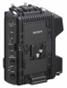
Names and Functions of Parts qf Screw holes for V-wedge shoe attachment of HD viewfinder qd TALLY switch qs RET 1 button qa RET button / RET 2/3/4 switch 0 CALL button 9 INTERCOM line switch 8 POWER switch / lamp 7 INTERCOM volume control 6 MIC switch 5 PGM volume control wf CCU connector wd DC OUT - Sony CA-FB70 | Operating Instructions - Page 8
a Cable clamp attachment Attaches the supplied cable clamp belt. b Accessory screw holes These comprise of a U1/4"-20 screw hole to secure an accessory, four screw holes to secure the supplied accessory fitting shoe (for the DXF-C50WA Electronic Viewfinder), and four screw holes to secure the - Sony CA-FB70 | Operating Instructions - Page 9
"DC IN" in "Pin assignment" on page 24. t Screw hole for camera/ camcorder A screw hole to fix the camera or camcorder. Use the screws for CA bracket. 9 Names and Functions of Parts - Sony CA-FB70 | Operating Instructions - Page 10
u INTERCOM connector (XLR 5pin) Used for input and output of intercom audio signals if an XLR 5-pin headset is connected. For information on pin assignment, see "INTERCOM" in "Pin assignment" on page 23. v PROMPTER connector (BNC) For output of the VBS prompter signal when a CCU is connected. w DC - Sony CA-FB70 | Operating Instructions - Page 11
Return Video Input HXC-D70 HD Color Camera Prompter Sync Input Video Input Optical Composite Cable1) CA-FB70 HD Camera Adaptor or PMW-5002)/3503)/3203) Prompter Solid-State Memory Camcorder Video Output HXCU-FB70 HD Camera Control Unit HD SDI/SD SDI/VBS/ HDMI Video Outputs AC Power CCA - Sony CA-FB70 | Operating Instructions - Page 12
Monitor Return Video Input Prompter Sync Input Video Input Single-Mode Optical Fiber Cable (Pair)1) CA-FB70 HD Camera Adaptor or PMW-5002)/3503)/3203) Solid-State Memory Camcorder Prompter Video Output HXCU-FB70 HD Camera Control Unit HD SDI/SD SDI/VBS/ HDMI Video Outputs AC Power CCA-5 Cable - Sony CA-FB70 | Operating Instructions - Page 13
Mode Optical Fiber Cable2) or CA-FB70 HD Camera Adaptor HXCE-FB70 Power Supply Unit HXCU-FB70 HD Camera Control Unit PMW series Remote Control Panel 1) The maximum transmission distance is 250 m (820 ft) when Sony CCFN-25/50/100 Hybrid Fiber Cable is used. 2) The maximum transmission distance is - Sony CA-FB70 | Operating Instructions - Page 14
bracket on the battery attachment shoe of the camera or camcorder using the two screws. 50P cover Attachment screws CA bracket 3 Slide down the adaptor from the upper side of the battery attachment shoe of the camera/ camcorder. 4 Tighten the attachment screws at the top (2) - Sony CA-FB70 | Operating Instructions - Page 15
Connecting a Camera Control Unit (CCU) When operating the camera in a system with a CCU, connect between the CCU connector of the adaptor and the CAMERA connector of the CCU. When required, secure the cable to the adaptor, using the supplied cable clamp belt. To use the cable clamp belt 1 Insert the - Sony CA-FB70 | Operating Instructions - Page 16
Attaching the Accessory Shoe Kit When you attach the DXF-51 or DXFC50WA Electronic Viewfinder, screw the supplied accessory shoe kit to the accessory shoe holes of the adaptor (four holes), then attach the viewfinder to the accessory shoe. To attach the accessory shoe Screw (K3×6) Accessory shoe - Sony CA-FB70 | Operating Instructions - Page 17
SIDE TONE level of the headset The displayed items in the above menu are as follows: Intercom1 (CAM): Intercom settings of the HXC-D70 Intercom2 (CA): Intercom settings of the adaptor When you do not use the INTERCOM connector of the HXC-D70, set the INTERCOM ON/OFF switch of the - Sony CA-FB70 | Operating Instructions - Page 18
to an intercom system and configuration of the settings, contact your Sony dealer. Starting the System 1 Attach the adaptor to the camera/ to set the video format for the camera/camcorder, adaptor and CCU. The adaptor supports the following video formats. • 1920×1080/59.94i • 1280×720/59.94P • - Sony CA-FB70 | Operating Instructions - Page 19
the CCU (HXCU-FB70). 2 When connected to the PMW-500/350/320 Solid-State Memory Camcorder As PMW-500/350/320 supports video formats that information on the mode setting of the camcorder, refer to the operating instructions of the camcorder. • If video formats are inconsistent between the adaptor - Sony CA-FB70 | Operating Instructions - Page 20
Error Messages When an error is detected, an error message shown in the below table appears. Since the adaptor does not have a display, the message is displayed in the menu of the CCU or the remote control panel. The adaptor also alarms it by blinking the POWER lamp (green). POWER Display in the - Sony CA-FB70 | Operating Instructions - Page 21
Important Notes on Operation Use and storage locations Store in a level, ventilated place. Avoid using or storing the adaptor in the following places. • In excessive heat or cold. Operating temperature range is -10°C to + 45°C (14°F to 113°F). When connected to the camcorder, the operating - Sony CA-FB70 | Operating Instructions - Page 22
5 A DC IN XLR 4-pin, male, DC12 V DC OUT 4-pin, female DC 12 V, maximum rated current 1.5 A Supplied Accessories Operating Instructions Japanese/English (1) CD-ROM (1) Warranty booklet (1) Cable clamp belt (1 set) CA bracket (1) Screws for CA bracket (2) Accessory shoe kit (1) 22 Specifications - Sony CA-FB70 | Operating Instructions - Page 23
Solid-State Memory Camcorder HXCU-FB70 HD Camera Control Unit HXCE-FB70 Power Supply Unit DXF-51 signal composite cable with the connectors specified in this manual in order to comply with the limit for EMC that the unit is operating properly before use. SONY WILL NOT BE LIABLE FOR DAMAGES OF ANY KIND - Sony CA-FB70 | Operating Instructions - Page 24
DC IN 1 4 2 3 CCU No. Signal IN/ Specifications OUT No. 1 EXT - GND for DC (+) A DC (C) 2 NC 3 NC B No connection 1 No connection 4 EXT IN +11 to +17 V dc 2 DC (H) 3 4 DC OUT 41 32 No. Signal IN/ OUT 1 UNREG - GND 2 NC 3 NC 4 UNREG OUT OUT Specifications GND for UNREG OUT No - Sony CA-FB70 | Operating Instructions - Page 25
Sony Corporation
-
 1
1 -
 2
2 -
 3
3 -
 4
4 -
 5
5 -
 6
6 -
 7
7 -
8
-
9
-
10
-
11
-
12
-
13
-
14
-
15
-
16
-
17
-
18
-
19
-
20
-
21
-
22
-
23
-
24
-
25
 |
 |

4-445-031-
11
(1)
© 2012 Sony Corporation
HD Camera Adaptor
Operating Instructions
Before operating the unit, please read this manual thoroughly
and retain it for future reference.
CA-FB70