Sony CDX-SW200 Installation/Connections Instructions
Sony CDX-SW200 - Fm/am Compact Disc Player Manual
 |
View all Sony CDX-SW200 manuals
Add to My Manuals
Save this manual to your list of manuals |
Sony CDX-SW200 manual content summary:
- Sony CDX-SW200 | Installation/Connections Instructions - Page 1
3-261-841-61 (1) 2 A FM/AM Compact Disc Player Installation/Connections Instalación/Conexiones B AUDIO OUT REAR CDX-SW200 © 2004 Sony Corporation Printed in Korea 1 1 2 3 × 4 4 5 × 2 Equipment used in illustrations (not supplied) Equipo utilizado en las ilustraciones (no suministrado) - Sony CDX-SW200 | Installation/Connections Instructions - Page 2
the speakers, turn the unit off. • Use speakers with an impedance of 4 to 8 ohms unit. • To avoid a malfunction, do not use the built-in speaker leads installed in your car if the unit de fuente de alimentación". 3 Para conectar a AMP REMOTE IN del amplificador de potencia opcional Esta conexión - Sony CDX-SW200 | Installation/Connections Instructions - Page 3
ón en la dirección correcta. c 2 Face the hook inwards. 5 El gancho debe encontrarse en la parte interior. c c 1 51 1 2 console al salpicadero/consola central Bracket Soporte Bracket Soporte Existing parts supplied with your car Piezas existentes suministradas con su automóvil 2 max. - Sony CDX-SW200 | Installation/Connections Instructions - Page 4
unit in a Japanese car (6) You may not be able to install this unit in some makes of Japanese cars. In such a case, consult your Sony dealer. Note To prevent malfunction, install como se muestra en la ilustración, y después presione la parte izquierda hasta que la unidad encaje en su lugar. Extracci
-
 1
1 -
 2
2 -
 3
3 -
 4
4
 |
 |
AUDIO OUT REAR
© 2004 Sony Corporation
Printed in Korea
3-261-841-
61
(1)
Cautions
• This unit is designed for negative ground 12 V DC
operation only.
• Do not get the leads under a screw, or caught in
moving parts (e.g. seat railing).
• Before making connections, turn the car ignition
off to avoid short circuits.
• Connect the
yellow
and
red
power input leads
only after all other leads have been connected.
•
Run all ground leads to a common ground
point.
• Be sure to insulate any loose unconnected leads
with electrical tape for safety.
• The use of optical instruments with this product
will increase eye hazard.
Notes on the power supply lead (yellow)
• When connecting this unit in combination with
other stereo components, the connected car
circuit’s rating must be higher than the sum of
each component’s fuse.
• When no car circuits are rated high enough,
connect the unit directly to the battery.
Parts Iist (
1
)
• The numbers in the list are keyed to those in the
instructions.
• The bracket
1
and the protection collar
3
are
attached to the unit before shipping. Before
mounting the unit, use the release keys
5
to
remove the bracket
1
and the protection collar
3
from the unit. For details, see “Removing the
protection collar and the bracket (
4
)” on the
reverse side of the sheet.
•
Keep the release keys
5
for future use as they
are also necessary if you remove the unit from
your car.
Caution
Handle the bracket
1
carefully to avoid injuring
your fingers.
Note
Before installing, make sure that the catches on
both sides of the bracket
1
are bent inwards 2 mm
(
3
/
32
in).
If the catches are straight or bent outwards, the unit
will not be installed securely and may spring out.
Installation/Connections
Instalación/Conexiones
FM/AM
Compact Disc
Player
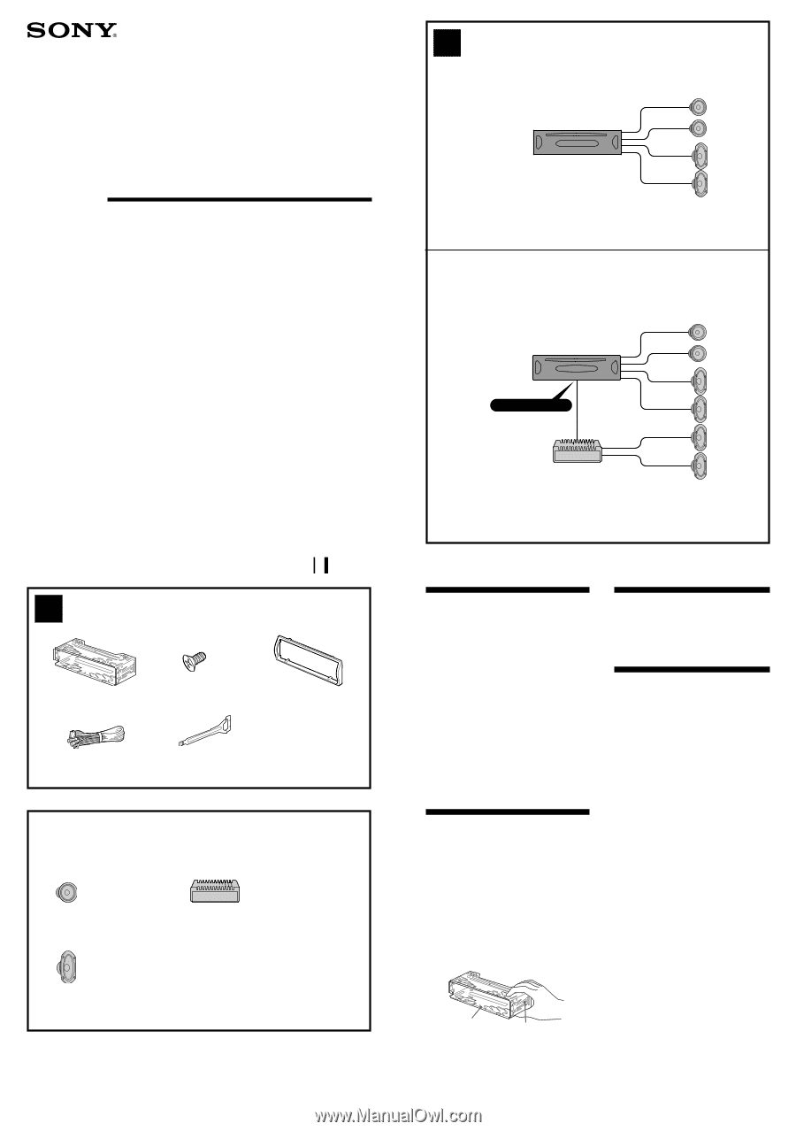
Connection example (
2
)
Notes
(
2
-B)
• Be sure to connect the ground lead before
connecting the amplifier.
• If you connect an optional power amplifier and
do not use the built-in amplifier, the beep
sound will be deactivated.
Connection diagram (
3
)
1
To a metal surface of the car
First connect the black ground lead, then
connect the yellow and red power input leads.
2
To the power antenna control lead or power
supply lead of antenna booster amplifier
Notes
• It is not necessary to connect this lead if
there is no power antenna or antenna
booster, or with a manually-operated
telescopic antenna.
• When your car has a built-in FM/AM antenna
in the rear/side glass, see “Notes on the
control and power supply leads.”
3
To AMP REMOTE IN of an optional power
amplifier
This connection is only for amplifiers.
Connecting any other system may damage the
unit.
4
To the +12 V power terminal which is
energized in the accessory position of the
ignition key switch
Notes
• If there is no accessory position, connect to
the +12 V power (battery) terminal which is
energized at all times.
Be sure to connect the black ground lead to
a metal surface of the car first.
• When your car has a built-in FM/AM antenna
in the rear/side glass, see “Notes on the
control and power supply leads.”
5
To the +12 V power terminal which is
energized at all times
Be sure to connect the black ground lead to a
metal surface of the car first.
A
B
1
4
5
Equipment used in illustrations (not supplied)
Equipo utilizado en las ilustraciones (no suministrado)
Rear speaker
Altavoces traseros
Front speaker
Altavoces delanteros
1
Power amplifier
Amplificador de potencia
×
4
2
×
2
3
CDX-SW200
1
Catch
2