Sony DSC-P41 Service Manual
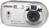
Sony DSC-P41 - Cyber-shot Digital Still Camera Manual
 |
View all Sony DSC-P41 manuals
Add to My Manuals
Save this manual to your list of manuals |
Sony DSC-P41 manual content summary:
- Sony DSC-P41 | Service Manual - Page 1
DSC-P41/P43 SERVICE MANUAL Ver 1.0 2004.04 Revision History How to use Acrobat Reader Photo: DSC-P43 2 LEVEL DSC-P41 US Model DSC-P43 Hong Kong Model Tourist Model Japanese Model DSC-P41/P43 and 5-10 to 5-14 The above-described information is shown in service manual Level 3. DIGITAL STILL CAMERA - Sony DSC-P41 | Service Manual - Page 2
(DSC-P41 only) • Battery case (1) • BC-CS2A/CS2B Ni-MH Battery charger (1) (DSC-P43 only) • Power cord (mains lead) (1) (DSC-P43 only) • USB cable (1) • A/V connecting cable (1) (DSC-P43 only) • Wrist strap (1) • "Memory Stick" (16MB) (1) • CD-ROM (USB driver: SPVD-012) (1) • Operating Instructions - Sony DSC-P41 | Service Manual - Page 3
DSC-P41/P43 SAFETY-RELATED COMPONENT WARNING!! COMPONENTS IDENTIFIED BY MARK 0 OR DOTTED LINE WITH MARK 0 ON THE SCHEMATIC DIAGRAMS AND IN THE PARTS LIST ARE CRITICAL TO SAFE OPERATION. REPLACE THESE COMPONENTS WITH SONY PARTS WHOSE PART NUMBERS APPEAR AS SHOWN IN THIS MANUAL OR IN SUPPLEMENTS - Sony DSC-P41 | Service Manual - Page 4
DSC-P41/P43 Section TABLE OF CONTENTS Title Page 1. SERVICE NOTE 1-1. Note for Repair 1-1 1-2. Discharging of the ST-098 Board's Charging Capacitor (C852 1-1 1-3. Description on Self-diagnosis Display 1-2 2. DISASSEMBLY 2-1. Flow Chart 2-1 2-2. SY-101 Board Service Position 2-3 2-3. - Sony DSC-P41 | Service Manual - Page 5
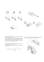
SECTION 1 SERVICE NOTE DSC-P41/P43 1-1. NOTE FOR REPAIR Make sure that the flat cable and flexible board are not cracked of bent at the terminal. Do not insert the cable - Sony DSC-P41 | Service Manual - Page 6
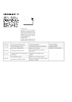
DSC-P41/P43 1-3. DESCRIPTION ON SELF-DIAGNOSIS DISPLAY Self-diagnosis display • C: ss: ss You can reverse the camera malfunction yourself. (However, contact your Sony dealer or local authorized Sony service facility when you cannot recover from the camera malfunction.) • E: ss: ss Contact your Sony - Sony DSC-P41 | Service Manual - Page 7
about 10 seconds. 2 1 Mic unit flexible: CN707 2 DC motor harness: CN602 3 Front cabinet R:1 kΩ/1 W (Part code: 1-215-869-11) ST-0958 Capacitor 1 4 2 DSC-P41/P43 HELP 3 5 4 21 1 Caution label 2 Tape (A) HELP 3 FP-853: CN702 4 FP-856: CN601 5 Lens block 3 9 2 qs 8 9 1 1 Screw (M1.7) x2 - Sony DSC-P41 | Service Manual - Page 8
DSC-P41/P43 2-2. SY-101 BOARD SERVICE POSITION 5 3 6 4 22 1 3 1 2 3 9 1 2 qs 4 8 9 qd 0 qa 7 6 5 5 2 1 3 5 4 21 Rear cabinet block FP-860 flexible board Flush unit ST-098 board Control switch block MS board SY-101 board Color monitor DSC-P43 only Lens block AC power adaptor - Sony DSC-P41 | Service Manual - Page 9
DSC-P41/P43 2-3. CIRCUIT BOARDS LOCATION SW-420 ST-098 SY-101 (including CH-146) MS (FP-861) CH-146 (included in SY-101) CD-501 Board Name Function CD-501 CCD IMAGER CH-146 CCD SIGNAL PROCESS (included in SY-101) MS (FP-861) MEMORY STICK CONNECTOR ST-098 FLASH DRIVE SW-420 CONTROL - Sony DSC-P41 | Service Manual - Page 10
DSC-P41/P43 HELP Sheet attachment positions and procedures of processing the flexible boards/harnesses are shown. Tape (A) Caution label SY-101 board Tape (A) HELP - Sony DSC-P41 | Service Manual - Page 11
DSC-P41/P43 3. BLOCK DIAGRAMS Link OVERALL BLOCK DIAGRAM (1/2) OVERALL BLOCK DIAGRAM (2/2) POWER BLOCK DIAGRAM (1/2) POWER BLOCK DIAGRAM (2/2) - Sony DSC-P41 | Service Manual - Page 12
DSC-P41/P43 IC304 47 1 CLOCK 5 GENERATOR (2/8) X301 54MHz 27MHz IC302 CAMERA DSP (2/8) E1 AB21 VER EXT CLK CAM SO, XCAM SCK AA8 IC501 MC CAM, SH DSP, FLASH (4/8) MC XCS IC 302REG MC XCS LED DRIVE D703 (MS ACCESS) MS BOARD MEMORY (FP-861 FLEXIBLE BOARD) STICK MC MS DIO, MC MS BS, CN705 - Sony DSC-P41 | Service Manual - Page 13
DSC-P41/P43 3. BLOCK DIAGRAMS 3-2. 501 BOARD (2/2) D803 SELF TIMER/ RECORDING D801 (AE/AF LOCK) D802 (FLASH CHARGE) CN801 (2/2) XTALLY LED 38 XAE LOCK LED 37 XCHARGE LED 36 CN702 AD2 39 2 MODE DIAL0 38 S261 MOVIE STILL VIEW A : VIDEO SIGNAL A : AUDIO SIGNAL A : VIDEO/AUDIO SIGNAL J001 DC IN - Sony DSC-P41 | Service Manual - Page 14
ST 5V CAM 15.5V A 3.1V CAM -7.5V/-8.0V A POWER 2 (PAGE 3-7) PANEL 13.5V D035 LED A LED K BL THH BL LEV SYS DD ON 05 3-5 3-6 DSC-P41/P43 - Sony DSC-P41 | Service Manual - Page 15
35 D801 (AE/AF LOCK) D802 (FLASH CHARGE) MS BOARD (FP-861 FLEXIBLE BOARD) Q704 CN705 9 CN001 VCC 9 MEMORY STICK D 1.2V L152 L153 A 2.8V AU 2.8V IC151 AUDIO AMP (6/8) D 2.8V D 1.2V L301 FB304 FB301 FB305 DSC-P43 IC301 VIDEO AMP (2/8) IC302 CAMERA DSP (2/8) XLENZ RST LED PI006 W2 A 5V - Sony DSC-P41 | Service Manual - Page 16
-861 FLEXIBLE BOARD MICROPHONE UNIT (MA-001) CN001 10 VSS 9 VCC 8 SCLK 7 DATA3 6 INT 5 DATA2 4 DIO 3 DATA1 2 BS 1 VSS SW-420 BOARD 1 11 10 12 MEMORY STICK MEMORY STICK 4-2 DSC-P41/P43 FRAME - Sony DSC-P41 | Service Manual - Page 17
DSC-P41/P43 4-2. SCHEMATIC DIAGRAMS Link CD-501 BOARD (CCD IMAGER) SW-420 BOARD (CONTROL SWITCH, LCD DRIVE) ST-098 BOARD (FLASH DRIVE) MS BOARD (FP-861 FLEXIBLE BOARD) (MEMORY STICK CONNECTOR) FP-860 FLEXIBLE BOARD (JACK) MICROPHONE UNIT (MA-001) CONTROL SWITCH BLOCK (RL51510) COMMON NOTE FOR - Sony DSC-P41 | Service Manual - Page 18
4-2. SCHEMATIC DIAGRAMS DSC-P41/P43 4-2. SCHEMATIC DIAGRAMS THIS NOTE IS COMMON FOR SCHEMATIC DIAGRAMS (In waveform) • Voltages and waveforms are measured between the measurement points and ground when camera shoots color bar chart of pattern box. They are reference values and reference - Sony DSC-P41 | Service Manual - Page 19
FLASH CHARGE) R814 82 D801 SML-510MWT86S (AE/AF LOCK) R815 82 D803 SML-310LTT86 (SELE TIMER/RECORDING) R816 820 SIGNAL PATH VIDEO SIGNAL Y/CHROMA REC 4-7 CD-501 BOARD 7 8 9 10 11 DSC-P41/P43 been replaced, carry out all the adjustments for the camera section. • As the CCD imager may be - Sony DSC-P41 | Service Manual - Page 20
Schematic diagrams of the CH-146 and SY-101 boards are not shown. Pages from 4-9 to 4-26 are not shown. - Sony DSC-P41 | Service Manual - Page 21
4-2. SCHEMATIC DIAGRAMS SW-420 BOARD DSC-P41/P43 For Schematic Diagram • Refer to page 4-43 for printed wiring board. 1 2 3 4 5 6 7 SWITCH) STILL R253 1200 VIEW R262 1200 1Pin R252 1500 R251 3300 R256 1500 S251 (FLASH) S256 S254 (SPOT METERING) (SET) S252 S255 (REVIEW) (SELF - Sony DSC-P41 | Service Manual - Page 22
DSC-P41/P43 4-2. SCHEMATIC DIAGRAMS For Schematic Diagram • Refer to page 4-45 for printed wiring board. 1 2 3 4 5 ST-098 BOARD A FLASH DRIVE (ST BLOCK) XX MARK:NO MOUNT NO MARK:REC/PB MODE B C R851 2200 0 0 Q851 CPH3235-S-TL-E TRANS DRIVE R853 1800 R855 150 T851 4 5 P 1 3 S C851 - Sony DSC-P41 | Service Manual - Page 23
2 BS 1 VSS C D 05 STATIC_GND SIGNAL PATH VIDEO SIGNAL Y/CHROMA REC PB AUDIO SIGNAL 1 11 10 12 6 7 MEMORY STICK MEMORY STICK MS BOARD FP-860 FLEXIBLE BOARD DSC-P41/P43 For Schematic Diagram • Refer to page 4-48 for printed wiring board. 1 2 3 4 5 6 7 FP-860 FLEXIBLE BOARD A JACK - Sony DSC-P41 | Service Manual - Page 24
DSC-P41/P43 4-2. SCHEMATIC DIAGRAMS 1 2 3 4 A MICROPHONE UNIT (MA-001) MICROPHONE UNIT (MA-001) is replaced as block, so that PRINTED WIRING BOARD is omitted. B C D 05 SW1 LENS COVER - Sony DSC-P41 | Service Manual - Page 25
DSC-P41/P43 4-3. PRINTED WIRING BOARDS Link CD-501 BOARD SW-420 BOARD ST-098 BOARD MS BOARD (FP-861 FLEXIBLE BOARD) FP-860 FLEXIBLE LOCATION FLEXIBLE BOARDS LOCATION Board Name CD-501 SW-420 ST-098 MS (FP-861) Function CCD IMAGER CONTROL SWITCH, LCD DRIVE FLASH DRIVE MEMORY STICK CONNECTOR - Sony DSC-P41 | Service Manual - Page 26
4-3. PRINTED WIRING BOARDS DSC-P41/P43 4-3. PRINTED WIRING BOARDS THIS NOTE IS COMMON FOR PRINTED WIRING BOARDS • : Uses unleaded solder. • : Circuit board : Flexible board Pattern from the side which enables seeing. : - Sony DSC-P41 | Service Manual - Page 27
FB802 D 05 1 1-860-287- 2 11 3 1 39 4-3. PRINTED WIRING BOARDS MOUNTED PARTS LOCATION DSC-P41/P43 CD-501 BOARD (SIDE B) D803 KA SELF TIMER/ D803 RECORDING AK D801 (AE/AF LOCK) D801 A D802 (FLASH CHARGE) AK D802 B 3 05 C806 R804 R803 C R809 Q803 E C B D 1-860-287- 11 - Sony DSC-P41 | Service Manual - Page 28
Printed wiring boards of the CH-146 and SY-101 boards are not shown. Pages from 4-39 to 4-42 are not shown. - Sony DSC-P41 | Service Manual - Page 29
DSC-P41/P43 SW-420 Note for Printed Wiring Board (See page 4-35). : Uses unleaded solder. C219 R211 BC E 3 4 21 Q201 D202 S261 VIEW STILL MOVIE S253 S257 A S261 W D-Zoom T R261 R252 C212 R262 R210 S251 (FLASH) S252 S252 (REVIEW) S255 S251 S254 S255 R201 C207 R251 876 C215 D201 - Sony DSC-P41 | Service Manual - Page 30
Note for Printed Wiring Board (See page 4-35). : Uses unleaded solder. 4-2. SCHEMATIC DIAGRAMS 4-3. PRINTED WIRING BOARDS MOUNTED PARTS LOCATION DSC-P41/P43 ST-098 BOARD (SIDE A) FLASH UNIT Q852 SG D 31 45 IC851 LND851 A 2 L851 1 3 05 1 LND853 2 LND852 R854 R853 CN851 12 R852 R855 - Sony DSC-P41 | Service Manual - Page 31
) VLL_3V BT001 05 LI_GND BT001 BATTERY, LITHIUM SECONDARY F X FP-860 2 3 DSC-P43 2 1 A/V OUT J002 (MONO) 4 1-860-200- Note: FP-860 flexible board is replaced as block, but BT001 and SP901 are not included in FP-860 flexible board. 41 : DSC-P43 51 : DSC-P41 MS (FP-861), FP-860 4-47 4-48 - Sony DSC-P41 | Service Manual - Page 32
C-2 C809 C-1 C810 C-3 CN801 B-3 * D801 A-1 * D802 A-1 * D803 A-1 FB801 C-2 FB802 D-1 IC801 B-2 Q801 C-1 Q802 C-2 * Q803 C-1 Q804 B-1 R801 C-1 R802 C-2 * R803 C-1 * R804 C-1 R805 C-2 R806 A-1 R807 A-1 * R809 C-1 R814 B-3 R815 A-3 R816 A-3 DSC-P41/P43 no mark : side A * mark : side B 4-49 CD-501 - Sony DSC-P41 | Service Manual - Page 33
Mounted parts location of the CH-146 and SY-101 boards are not shown. Pages 4-50 and 4-51 are not shown. - Sony DSC-P41 | Service Manual - Page 34
DSC-P41/P43 4-3. PRINTED WIRING BOARDS SW-420 BOARD * C201 B-1 * C202 B-2 * C203 B-2 * C204 B-2 * C205 B-1 * C206 C-1 * C207 A-1 * C208 C-2 * C209 B-1 * C210 B-1 * C211 C-1 * C212 A-1 * C213 B-1 * C214 C-1 C216 B-3 C217 B-3 C218 B-3 CN201 C-2 CN202 C-3 - Sony DSC-P41 | Service Manual - Page 35
DSC-P41/P43 NOTE 5. REPAIR PARTS LIST NOTE: Characters A to Z of the electrical parts list indicate location of exploded views in which the desired HOLDER BLOCK SECTION REAR CABINET BLOCK SECTION Link CD-501 BOARD MS BOARD ELECTRICAL PARTS LIST B ST-0985 BOARD C C SW-420 BOARD D ACCESSORIES - Sony DSC-P41 | Service Manual - Page 36
5. REPAIR PARTS LIST SECTION 5 REPAIR PARTS LIST DSC-P41/P43 NOTE: • -XX, -X mean standardized parts, so they may have some differences from the original one. • Items marked "*" are not stocked since they are seldom required for routine service. Some delay should be anticipated when ordering these - Sony DSC-P41 | Service Manual - Page 37
DSC-P41/P43 5. REPAIR PARTS LIST 5-1. EXPLODED VIEWS 5-1-1. FRONT CABINET BLOCK No. Description X-2021-517-1 CABINET (FRONT) ASSY (450) (P41) X-3954-373-1 CABINET (FRONT) ASSY (510) (P43) 3-080-977-01 TRIPOD 3-080-204-21 SCREW, TAPPING, P2 3-090-844-01 WINDOW (510), OVF Ref. No. 5 6 7 8 M901 - Sony DSC-P41 | Service Manual - Page 38
5. REPAIR PARTS LIST 5-1-2. LENS BLOCK SECTION DSC-P41/P43 59 58 52 51 57 61 CD-501 60 IC801 54 (Note 1, 2) 55 53 56 Ref. No. 51 52 53 54 55 Part No. Description 8- - Sony DSC-P41 | Service Manual - Page 39
11 FLASH UNIT 3-090-797-01 CUSHION, SP 1-860-200-41 FP-860 FLEXIBLE BOARD (P43) 1-860-200-51 FP-860 FLEXIBLE BOARD (P41) SERVICE) (including CP900 (CH-146 board)) (P41) 1-860-199-11 FP-859 FLEXIBLE BOARD 1-860-192-11 FP-852 FLEXIBLE BOARD 3-941-343-21 TAPE (A) 2-067-931-01 SHEET, MS SHEET METAL (P43 - Sony DSC-P41 | Service Manual - Page 40
not supplied ns 151 156 154 152 151 SW-420 153 D901 LCD901 DSC-P41/P43 155 Ref. No. 151 152 153 154 154 Part No. Description (P43) 156 2-022-234-01 SHEET (510), CCD RADIATION 0 D901 1-478-465-21 BLOCK, LIGHT GUIDE PLATE (1.5) (P41) 0 D901 1-478-465-11 BLOCK, LIGHT GUIDE PLATE (1.5) (P43) - Sony DSC-P41 | Service Manual - Page 41
DSC-P41/P43 CD-501 5-2. ELECTRICAL PARTS LIST Ref. No. Part No. Description D801 D802 D803 8-719-075-29 DIODE SML-510MWT86S (AE/AF LOCK) 8-719-077-34 DIODE SML-310YTT86 (FLASH CHARGE) 8-719-064-07 DIODE SML-310LTT86 (SELF TIMER/RECORDING) < FERRITE BEAD > FB801 1-414-228-11 INDUCTOR, - Sony DSC-P41 | Service Manual - Page 42
DSC-P41/P43 MS ST-098 SW-420 Ref. No. Part No. Description A-7113-208-A MS BOARD, COMPLETE Ref. No. Part No. Description C204 1-164-943-11 CERAMIC CHIP 0.01uF 10% 16V C205 1-125-777-11 CERAMIC CHIP 0.1uF 10% 10V < CONNECTOR > CN001 1-815-572-61 CONNECTOR, MEMORY STICK A-7113-098-A ST-098 - Sony DSC-P41 | Service Manual - Page 43
-138-82 SWITCH, KEY BOARD (v (FLASH)) 1-771-138-82 SWITCH, KEY BOARD (b (REVIEW)) 1-786-157-31 TACTILE SWITCH (D-Zoom STILL/MOVIE (MODE SWITCH)) 1-771-138-82 SWITCH, KEY BOARD (RESET) Description Electrical parts list of the SY-101 board is not shown. Pages 5-10 to 5-14 are not shown. DSC-P41/P43 - Sony DSC-P41 | Service Manual - Page 44
Wrist strap (1) 3-089-555-01 "Memory Stick" (16MB) (1) (not supplied) Conversion Adaptor (1) (P43 only) 0 1-569-007-11 (E) 0 1-573-856-12 (JE) CD-ROM (SPVD-012 USB driver) (1) 3-091-338-01 (US, J) 3-091-339-01 (EXCEPT US, J) Other accessories 3-091-349-01 MANUAL, INSTRUCTION (for BASIC) (JAPANESE - Sony DSC-P41 | Service Manual - Page 45
DSC-P41/P43 9-876-743-31 Sony EMCS Co. - 58 - 2004D0500-1 ©2004.4 Published by DI Technical Support Section - Sony DSC-P41 | Service Manual - Page 46
functions on toolbar of the Adobe Acrobat Reader Ver5.0 (for Windows)] Toolbar Printing a text 1. Click the Print button . 2. board diagram successively. Note: The find function may not be applied to the Service Manual depending on the date of issue. Reversing the screens displayed once • To - Sony DSC-P41 | Service Manual - Page 47
Reverse Revision History Ver. Date History 1.0 2004.04 Official Release Contents - 987674331.pdf S.M. Rev. issued -
-
 1
1 -
 2
2 -
 3
3 -
 4
4 -
 5
5 -
 6
6 -
 7
7 -
8
-
9
-
10
-
11
-
12
-
13
-
14
-
15
-
16
-
17
-
18
-
19
-
20
-
21
-
22
-
23
-
24
-
25
-
26
-
27
-
28
-
29
-
30
-
31
-
32
-
33
-
34
-
35
-
36
-
37
-
38
-
39
-
40
-
41
-
42
-
43
-
44
-
45
-
46
-
47
 |
 |
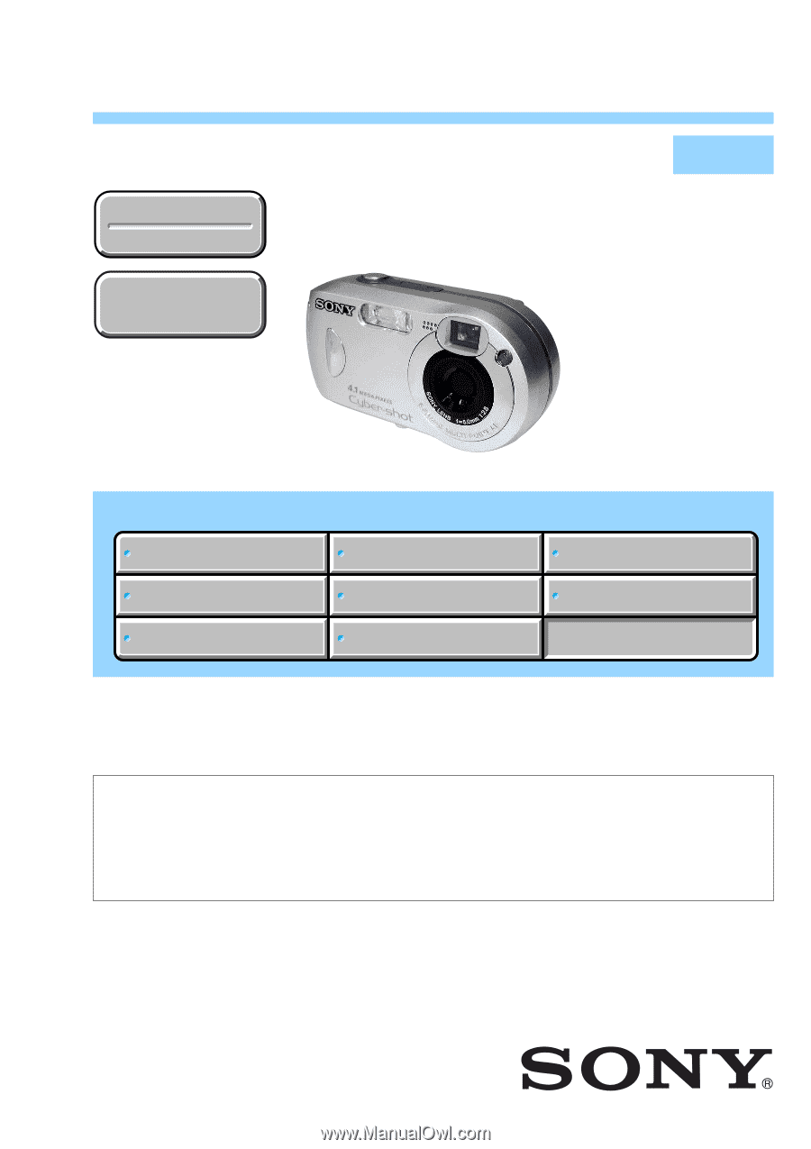
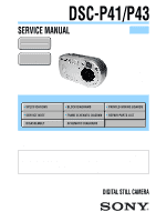
SERVICE MANUAL
LEVEL
2
Link
SERVICE NOTE
DISASSEMBLY
BLOCK DIAGRAMS
FRAME SCHEMATIC DIAGRAM
SCHEMATIC DIAGRAMS
PRINTED WIRING BOARDS
REPAIR PARTS LIST
SPECIFICATIONS
SERVICE NOTE
DISASSEMBLY
BLOCK DIAGRAMS
FRAME SCHEMATIC DIAGRAM
SCHEMATIC DIAGRAMS
PRINTED WIRING BOARDS
REPAIR PARTS LIST
SPECIFICATIONS
Link
Revision History
Revision History
DSC-P41/P43
How to use
Acrobat Reader
How to use
Acrobat Reader
•
For ADJUSTMENTS (SECTION 6), refer to SERVICE MANUAL, ADJ (987674351.pdf).
•
For INSTRUCTION MANUAL, refer to SERVICE MANUAL, LEVEL 1 (987674341.pdf).
•
Reference No. search on printed wiring boards is available.
•
HELP: Sheet attachment positions and procedures of processing the flexible boards/harnesses are shown.
Ver 1.0
2004.04
DIGITAL STILL CAMERA
On the CH-146 and SY-101 boards
This service manual procides the information that is premised
the circuit board replacement service and not intended repair
inside the CH-146 and SY-101 boards.
Therefore, schematic diagram, printed wiring board and
electrical parts list of the CH-146 and SY-101 boards are not
shown.
The following pages are not shown.
Schematic diagram
............
Pages 4-9 to 4-26
Printed wiring board
...........
Pages 4-39 to 4-42
Mounted parts location
.......
Pages 4-50 and 5-51
Electrical parts list
..............
Pages 5-7 and 5-10 to 5-14
The above-described information is shown in service
manual Level 3.
DSC-P41
US Model
DSC-P43
Hong Kong Model
Tourist Model
Japanese Model
DSC-P41/P43
Canadian Model
AEP Model
UK Model
E Model
Australian Model
Chinese Model
Korea Model
Argentine Model
Brazilian Model
Photo: DSC-P43