Sony DSC S500 Service Manual
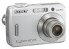
Sony DSC S500 - Cyber-shot Digital Camera Manual
 |
UPC - 027242692541
View all Sony DSC S500 manuals
Add to My Manuals
Save this manual to your list of manuals |
Sony DSC S500 manual content summary:
- Sony DSC S500 | Service Manual - Page 1
une pièce portant le numéro spécifié. In case of the lens assembly, main board, or main frame assembly failure, contact your local Sony Service Headquarter for the measures. DIGITAL STILL CAMERA DSC-S500 9-852-124-12 Sony EMCS Co. 2007H0800-1 © 2007.08 Published by Kohda TEC - Sony DSC S500 | Service Manual - Page 2
compliant, DPOF compatible Movies: AVI (Motion JPEG) Recording media Internal Memory (Approx. 25 MB) "Memory Stick Duo" (with MagicGate/ without MagicGate) "Memory Stick PRO Duo" "MagicGate Memory Stick Duo" Flash range When ISO set to Auto: approx. 0.5 m to 2.5 m (19 3/4 inches to 98 1/2 inches - Sony DSC S500 | Service Manual - Page 3
LINE WITH MARK 0 ON THE SCHEMATIC DIAGRAMS AND IN THE PARTS LIST ARE CRITICAL TO SAFE OPERATION. REPLACE THESE COMPONENTS WITH SONY PARTS WHOSE PART NUMBERS APPEAR AS SHOWN IN THIS MANUAL OR IN SUPPLEMENTS PUBLISHED BY SONY. ATTENTION AU COMPOSANT AYANT RAPPORT À LA SÉCURITÉ! LES COMPOSANTS IDENTIF - Sony DSC S500 | Service Manual - Page 4
Internal Memory 1-1 2. DISASSEMBLY 2-1. Disassembly 2-1 3. BLOCK DIAGRAMS 3-1. Overall Block Diagram 3-1 3-2. Power Block Diagram 3-2 4. REPAIR PARTS LIST 4-1. Exploded Views 4-1 4-1-1. Overall Section 4-1 4-1-2. Front Block 4-2 4-1-3. Main Frame Block 4-3 4-2. Accessories 4-4 DSC-S500 - Sony DSC S500 | Service Manual - Page 5
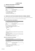
the data, execute formatting the internal memory.) Note: When replacing the camera, erase the data in internal memory of the board before replacement. Method for Copying the Data in Internal Memory Copy Copies all images in the internal memory to a "Memory Stick Duo". OK See the following - Sony DSC S500 | Service Manual - Page 6
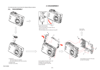
3 Pull the battery case in the direction of arrow A. 1 1 2 1 2 4 3 1 Mode dial Take it off pulling over to upward. Push down adjusting rib width when attaching. 2 Shutter button 3 Shutter button spring DSC-S500 3 1 Two tapping screws (M1.7x3.5) silver 2 Middle cover assembly (right) 3 Tapping - Sony DSC S500 | Service Manual - Page 7
Tapping screw (M1.7x3.5) silver 4 LCD holder 5 TFT-LCD 1 3 4 2 1 2 1 From the MCU board 2 Front cover assembly Shorting jig 2 (1kΩ / 1W) Caution 1 2 1 DSC-S500 3 1 Microphone fixed sheet 2 Microphone assembly 3 From the MCU board 1 Stroboscope block assembly 2 Discharging the capacitor - Sony DSC S500 | Service Manual - Page 8
RAMCLK RAMCLK_EN +2.5V DGND DDR +2.5V DGND MEMORY STICK U 12 ALE CLE WE WP RE R/B DGND ZOOM FOCUS IRIS SHUTTER MOTOR DRIVER C N2 7 PIN C N1 +3.3VD DGND UP DOWN RIGHT LEFT SET MENU DISPLAY TRASH MS_LED +3.3VD DGND J 2 F U N C TIO N KEY MS_LED 1 MS 2 LED GREEN SW BOARD 2 2 DSC-S500 3-1 - Sony DSC S500 | Service Manual - Page 9
CCD VL C C D1 0.01UK 2 M IC 1 0.1UF U 12 VCC 1 10UF 0.1UF X 2 N A N D FLASH 2 J6 10UF VCC2 MS CARD 2 1 2 1 #0 1 2 2.2UK #0 1 2 2 1 1 2 1 U8 +12V VD VH 0.01UK C D S1 -7.5V VD C107 #4. 2 RED 2 +3.3VD SW BOARD J2 F U N C TIO N KEY MS LED 1 2 BULE DSC-S500 3-2 - Sony DSC S500 | Service Manual - Page 10
2149-431-1 Cover Assy, Rear X-2149-248-1 Belt (left), Inner X-2109-765-1 Middle Cover Assy (right) 2-694-421-01 Screw TP1.7*16 Ref. No. 6 7 8 9 Part No. Description 2-699-483-01 LID, Battery Case 2-682-974-01 Mode Dial 2-682-975-01 Shutter Button 2-682-976-01 Shutter Button Spring DSC-S500 4-1 - Sony DSC S500 | Service Manual - Page 11
4-1-2. FRONT BLOCK 4. REPAIR PARTS LIST 51 53 52 52 Ref. No. 51 52 53 Part No. Description X-2149-247-1 Cover Assy, Front 2-682-984-01 Screw TP1.7*3.5 A-1188-384-A Jack Assy DSC-S500 4-2 - Sony DSC S500 | Service Manual - Page 12
local Sony Service Headquarter for the measures. (Note 2) The adjustment is not required after replacing the stroboscope block assembly or LCD. Ref. No. 105 106 107 Part No. Description 2-682-983-01 Screw TP1.7*20 2-682-993-01 Sheet, Microphone Fixed A-1188-556-A Microphone Assy DSC-S500 4-3 - Sony DSC S500 | Service Manual - Page 13
-ROM (Cyber-shot Application Software, handbook "Cyber-shot Handbook") 2-696-130-01 Note: This item is supplied with the unit as an accessory, but is not prepared as a service part. LR6 (size AA) Alkaline Battery (Note) Preparation Digital Still Camera Instruction Manual DSC-S500 Before operating - Sony DSC S500 | Service Manual - Page 14
Ver 1.1 2006.07 [Regarding Fuse 1] • MCU BOARD MANUFACTURER: Kamaya Electric Co., Ltd. TYPE: FCC16 162AD RATING: 1.6A R38 R104 R105 L4 C57 R47 R142 R411 R143 U16 C18 D4 D5 C189 C163 C197 C198 U17 C158 C98 J8 R141 R412 C47 R164 Q7 R163 Q24 R49 C9 Q29 F1 C402 C401 C7 C6 C15 C4 - Sony DSC S500 | Service Manual - Page 15
Ver 1.1 2006.07 [Regarding Fuse 2] • STROBE BOARD R15 R13 SW2 F1 Q3 LED1 TP5 Q4 TP1 SW1 R15 R13 SW2 F1 Q3 LED1 MANUFACTURER: Kamaya Electric Co., Ltd. TP5 SW1 TYPE: FCC10 801AD Q4 RATING: 800mA TP1 - Sony DSC S500 | Service Manual - Page 16
of accessories. • Addition of Repair Parts 4-1-3. MAIN FRAME BLOCK (See original service manual page 4-3) Former & : Points added portion. New Ref. No. Part No ns (Note 1) Description 108 Ref. No. 108 Part No. Description 3-100-837-01 HOLDER, MS CARD ) ns (Note 1) DSC-S500 9-852 - Sony DSC S500 | Service Manual - Page 17
click [OK]. Application of printing: To set a range to be printed within a Service Manual: The parts on the drawing pages (block diagrams, circuit diagrams, printed circuit boards) and parts to the Service Manual depending on the date of issue. (such as a button on cover and the table of contents page - Sony DSC S500 | Service Manual - Page 18
Regarding Fuse 1, Regarding Fuse 2 1.2 2006.09 Supplement-1 • Addition of Repair Parts (S1 DI06-046) 1.3 2007.08 Supplement-2 • Addition of Repair Parts (S2 DI07-052) • Please discard the SUPPLEMENT-1. Revision of Accessories S.M. Revised: Page 4-4 S.M. Rev. issued - Yes No Yes DSC-S500
-
 1
1 -
 2
2 -
 3
3 -
 4
4 -
 5
5 -
 6
6 -
 7
7 -
8
-
9
-
10
-
11
-
12
-
13
-
14
-
15
-
16
-
17
-
18
 |
 |
Revision History
Revision History
How to use
Acrobat Reader
How to use
Acrobat Reader
Internal memory
ON BOARD
Internal memory
ON BOARD
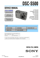
SERVICE MANUAL
Link
Link
Sony EMCS Co.
DSC-S500
SERVICE NOTE
SPECIFICATIONS
BLOCK DIAGRAMS
DISASSEMBLY
REPAIR PARTS LIST
Ver. 1.3
2007.08
DIGITAL STILL CAMERA
2007H0800-1
© 2007.08
Published by Kohda TEC
9-852-124-12
US Model
Canadian Model
AEP Model
UK Model
E Model
Australian Model
Hong Kong Model
Korea Model
The components identified by
mark
0
or dotted line with
mark
0
are critical for safety.
Replace only with part num-
ber specified.
Les composants identifiés par une
marque
0
sont critiques pour la
sécurité.
Ne les remplacer que par une pièce
portant le numéro spécifié.
DSC-S500
In case of the lens assembly, main board, or main frame assembly failure,
contact your local Sony Service Headquarter for the measures.