Sony DSC S730 Service Manual
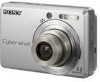
Sony DSC S730 - Cyber-shot Digital Camera Manual
 |
UPC - 027242724938
View all Sony DSC S730 manuals
Add to My Manuals
Save this manual to your list of manuals |
Sony DSC S730 manual content summary:
- Sony DSC S730 | Service Manual - Page 1
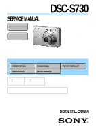
SERVICE MANUAL Ver. 1.0 2007.11 Revision History Internal memory ON BOARD DSC-S730 US Model Canadian Model AEP Model UK Model E Model Australian Model Hong Kong Model Chinese Model Korea Model Tourist Model Link SPECIFICATIONS SERVICE NOTE DISASSEMBLY BLOCK DIAGRAM REPAIR PARTS LIST The - Sony DSC S730 | Service Manual - Page 2
) (W/H/D, excluding protrusions) Mass: Approx. 189 g (6.7 oz) (including two batteries and strap, etc.) Microphone: Monaural Buzzer Exif Print: Compatible PRINT Image Matching III: Compatible PictBridge: Compatible Design and specifications are subject to change without notice. DSC-S730 - 2 - - Sony DSC S730 | Service Manual - Page 3
PARTS LIST ARE CRITICAL TO SAFE OPERATION. REPLACE THESE COMPONENTS WITH SONY PARTS WHOSE PART NUMBERS APPEAR AS SHOWN IN THIS MANUAL OR IN SUPPLEMENTS PUBLISHED BY SONY SONY. SAFETY CHECK-OUT After correcting the original service problem LEAD FREE DSC-S730 also be added to ordinary solder. - 3 - - Sony DSC S730 | Service Manual - Page 4
1-2. Method for Copying or Erasing the Data in Internal Memory 1-1 2. DISASSEMBLY 2-1. Disassembly 2-1 3. BLOCK DIAGRAM 3-1. Overall Block Diagram 3-1 4. REPAIR PARTS LIST 4-1. Exploded Views 4-1 4-1-1. Overall Section 4-1 4-1-2. Main Frame Block 4-2 4-2. Accessories 4-3 DSC-S730 - 4 - - Sony DSC S730 | Service Manual - Page 5
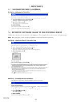
to it. You cannot choose a specific folder and copy images to it. The (Print order) marks on the images are not copied. Method for Formatting the Internal Memory This item does not appear when a "Memory Stick Duo" is inserted in the camera. Format Formats the internal memory. Note that formatting - Sony DSC S730 | Service Manual - Page 6
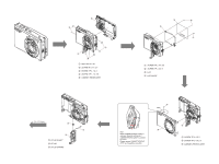
1 Open the BT LID 2 SCREW M 1.7 X 2.7 3 SCREW TP 1.7 X 4 4 SCREW TP 1.7 X 3.5 5 CABINET (REAR) ASSY 3 4 2 1 1 SCREW TP 1.4 X 3.5 2 SCREW TP 1.4 X 4 3 LCD 4 LCD PLATE DSC-S730 (To 2-2 Page) 3 1 2 1 BT LID SHAFT 2 BT LID 3 BT LID SPRING 2 plate 3 Note : When CABINET(FRONT) ASSY is removed, the - Sony DSC S730 | Service Manual - Page 7
seal removed when discharged. 1 STRAP SHAFT 2 SCREW TP 1.4 X 3 3 RL BLOCK DSC-S730 1 3 2 3 2 1 SCREW TP 1.7 X 3.5 2 SCREW TP 1.7 X 6.5 3 ST BLOCK ASSY 2-2 1 4 1 SCREW TP 1.4 X 2.5 2 SCREW TP 1.7 X 3.5 3 MAIN MOUNT 4 SUPPORT (JACK) 4 3 1 JACK LID 2 SCREW TP 1.4 X 3 3 LENS BLOCK ASSY 4 LID - Sony DSC S730 | Service Manual - Page 8
MEMORY STICK +13.4V BUZZER +3.1V D DGND UGND PC 6 4 3 2 1 32.768K Hz 3 4 +3.1V D Power 4 1 Out GND_3 3 2 GND_2 MIC 1 S P M0204HD5 MC4_4.72X3.76_173 G2412-0039-00 LENS BLOCK IRIS(METER) LENS ZOOM SENSOR ZOOM MOTOR FOCUS SENSOR FOCUS MOTOR IRIS MOTOR SHUTTER MOTOR 2 DSC-S730 - Sony DSC S730 | Service Manual - Page 9
LID, BT 9 3-286-702-01 SPRING, BT LID 10 3-286-703-01 LID, JACK Ref. No. 11 12 13 14 15 Part No. Description 3-287-023-11 SCREW M1.7 X 2.7 3-287-026-01 SCREW TP1.4 X 2.5 3-287-028-01 SCREW TP1.7 X TP1.4 X 3.5 18 3-296-921-01 SCREW TP1.4 X 4 19 3-299-366-01 SCREW TP1.7 X 3.5 DSC-S730 4-1 - Sony DSC S730 | Service Manual - Page 10
frame replacement, assemble original lens block assy and main board back after repaire. Ref. No. 101 102 103 104 105 Part No. Description 3-286-699-01 3-287-024-01 3-287-026-01 3-287-028-01 3-286-704-01 SUPPORT (JACK) SCREW TP1.4 X 3 SCREW TP1.4 X 2.5 SCREW TP1.7 X 3.5 FRAME, MAIN DSC-S730 4-2 - Sony DSC S730 | Service Manual - Page 11
LR6 (size AA) Alkaline Battery (Note 1) CD-ROM (Cyber-shot application software/ "Cyber-shot Handbook"/ "Cyber-shot Step-up Guide") *3-281-189-01 Cyber-shot Handbook(PDF) The CD-ROM supplied contains all of language version of the Instruction Manual in pdf (Cyber-shot Handbook.pdf) for printing - Sony DSC S730 | Service Manual - Page 12
Regarding Fuse MAIN BOARD F5 F3 DSC-S730 MANUFACTURER: KAMAYA ELECTRIC CO.,LTD. F5 TYPE: FCC10102AD RATING: 1.0A F3 MANUFACTURER: KAMAYA ELECTRIC CO.,LTD. TYPE: FCC16162AD RATING: 1.6A - Sony DSC S730 | Service Manual - Page 13
Reverse Revision History Ver. Date History 1.0 2007.11 Official Release Contents - 985223911.pdf S.M. Rev. issued - DSC-S730
-
 1
1 -
 2
2 -
 3
3 -
 4
4 -
 5
5 -
 6
6 -
 7
7 -
8
-
9
-
10
-
11
-
12
-
13
 |
 |
Sony EMCS Co.
DSC-S730
2007K0200-1
© 2007.11
Published by Kohda TEC
9-852-239-11
Revision History
Revision History
Internal memory
ON BOARD
Internal memory
ON BOARD
SERVICE MANUAL
Link
Link
SERVICE NOTE
SPECIFICATIONS
BLOCK DIAGRAM
DISASSEMBLY
REPAIR PARTS LIST
Ver. 1.0 2007.11
DIGITAL STILL CAMERA
US Model
Canadian Model
AEP Model
UK Model
E Model
Australian Model
Hong Kong Model
Chinese Model
Korea Model
Tourist Model
The components identified by
mark
or dotted line with
mark
are critical for safety.
Replace only with part num-
ber specified.
Les composants identifiés par une
marque
sont critiques pour la
sécurité.
Ne les remplacer que par une pièce
portant le numéro spécifié.
DSC-S730
In case of the lens block assy, main board, or main frame assembly failure,
contact your local Sony Service Headquarter for the measures.