Sony DVX-11A Installation/Connections
Sony DVX-11A - Car Mp3/dvd/cd Single Player Manual
 |
View all Sony DVX-11A manuals
Add to My Manuals
Save this manual to your list of manuals |
Sony DVX-11A manual content summary:
- Sony DVX-11A | Installation/Connections - Page 1
main Tipo de freno manual Parking brake switch cord wires under screws, or in moving parts (e.g., seat railing). •Before making connections, turn the car diagram (2) Example: When installing under the passenger seat. Note All the equipment other than the Sony DVD player DVX-11A and the remote control - Sony DVX-11A | Installation/Connections - Page 2
REAR AUDIO/ VIDEO OUT Remote control sensor*3 Capteur de la télécommande*3 Sensor del control remoto ceux-ci dans des pièces mobiles (par exemple, armature de si des instructions. Attention Manipulez le support ningún tornillo ni partes móviles (p. ej. DVD DVX-11A de Sony y del sensor del control - Sony DVX-11A | Installation/Connections - Page 3
tablero/consola central Bracket Support Abrazadera Bracket Support Abrazadera Existing parts supplied with your car Pièces existantes fournies transmitter Transmetteur de signal Transmisor de señal Remote control sensor To the mounting surface Capteur de la télécommande qg Vers la surface - Sony DVX-11A | Installation/Connections - Page 4
Japanese cars. In such a case, consult your Sony dealer. Note To prevent malfunction, install only with the supplied screws 3. Horizontal installation (7C) When you install the unit, be careful not to damage wiring or equipment on the other side of the mounting surface. Attaching the remote control
-
 1
1 -
 2
2 -
 3
3 -
 4
4
 |
 |

Installation diagram (
2
)
Example:
When installing under the passenger seat.
Note
All the equipment other than the Sony DVD player
DVX-11A and the remote control sensor is not
supplied.
Connecting the parking brake
cord (
3
)
Be sure to connect the parking cord (Light
green) of
5
to the parking brake switch cord.
The mounting position of the parking brake
switch cord depends on your car. Consult your
car dealer or your nearest Sony dealer for
further details.
Using the tap
Attach the tap
qs
to the end of the parking cord
(Light green) of
5
and the parking brake switch
cord.
Note
If the parking brake switch cord is too thin, connect
the parking cord (Light green) of
5
to the parking
brake switch cord directly without using the tap
qs
.
Connection diagram (
4
)
1
To a metal surface of the car
First connect the black ground lead, then
connect the yellow and red power input leads.
2
To the +12 V power terminal which is energized
in the accessory position of the ignition key
switch
Note
If there is no accessory position, connect to the
+12 V power (battery) terminal which is
energized at all times.
Be sure to connect the black ground lead to a
metal surface of the car first.
3
To the +12 V power terminal which is energized
at all times
Be sure to connect the black ground lead to a
metal surface of the car first.
4
To the parking brake switch cord
5
To a digital amplifier or audio device
Connect the optical cable RC-97/98 (not
supplied), etc., to a digital amplifier or audio
device equipped with a Dolby digital decoder.
© 2003 Sony Corporation
Printed in Japan
DVX-11A
3-255-986-
11
(1)
Installation/Connections
Installation/Raccordements
Instalación/Conexiones
Mobile DVD
Player
Foot brake type
Type pédale de frein
Tipo de freno de pedal
Hand brake type
Type frein à main
Tipo de freno manual
Parking brake switch cord
Cordon du capteur du frein à main
Cable de conmutación del freno de
estacionamiento
qs
Using the tap
Utilisation de la dérivation
Uso de la derivación
c
Connection box
Boîtier de raccordement
Caja de conexiones
Front speaker (Left)
Enceinte avant (Gauche)
Altavoz delantero (Izquierdo)
Rear speaker (Left)
Enceinte arrière (Gauche)
Altavoz trasero (Izquierdo)
Subwoofer
Haut-parleur extrêmes-graves
Altavoz potenciador de graves
Master unit
Unité principale
Unidad maestra
Front speaker (Right)
Enceinte avant (Droite)
Altavoz delantero (Derecho)
Rear speaker (Right)
Enceinte arrière (Droite)
Altavoz trasero (Derecho)
Headrest Monitor
Moniteur encastré dans l’appuie-tête
Monitor para reposacabezas
Overhead monitor
Écran plafonnier
Monitor portátil
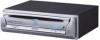
Sony DVD player DVX-11A
Lecteur DVD DVX-11A Sony
Reproductor de DVD DVX-11A de Sony
Remote control sensor
Capteur de la télécommande
Sensor del control remoto
2
Parking cord (Light green) of
5
Cordon du frein à main (vert clair)
5
Cable de estacionamiento (verde claro) de
5
Parking brake switch cord
Cordon du capteur du frein
à main
Cable de conmutación del
freno de estacionamiento
Parking brake switch cord
Cordon du capteur du frein
à main
Cable de conmutación del
freno de estacionamiento
1
3
×
4
8
9
4
6
5
7
qa
qs
q;
qf
qg
qd
qj
3
PM3
×
6
×
4
×
3
3
T5
×
8
×
2
qh
2
3
1
Cautions
•This unit is designed for negative ground 12 V
DC operation only.
•Do not pinch wires under screws, or in moving
parts (e.g., seat railing).
•Before making connections, turn the car
ignition off to avoid short circuits.
•Connect the
yellow
and
red
power input leads
only after all other leads have been connected.
•
Run all ground wires to a common ground
point.
•Be sure to insulate any loose unconnected
wires with electrical tape for safety.
•The use of optical instruments with this
product will increase the risk of eye injury.
•Control adjustments and procedures other
than those specified herein may result in
hazardous radiation exposure.
•For your safety, the monitor connected to the
FRONT VIDEO OUT can only be viewed when
the car is stopped and the parking brake
applied.
Be sure to connect the parking cord (Light
green) of
5
to the car’s parking brake switch
cord.
Notes on the power supply cord (yellow)
•When connecting this unit in combination with
other stereo components, the connected car
circuit’s rating must be higher than the sum of
each component’s fuse.
•When no car circuits are rated high enough,
connect the unit directly to the battery.
Parts Iist (
1
)
The numbers in the list are keyed to those in the
instructions.
Caution
Handle the bracket
1
carefully to avoid injuring
your fingers.
Note
Before installing, make sure that the catches on
both sides of the bracket
1
are bent inwards 2 mm
(
3
/
32
in). If the catches are straight or bent outwards,
the unit will not be installed securely and may spring
out.
×
2
1
Catch