Sony FWD-32LX1R Operating Instructions - Page 10
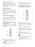
Optional adaptors Not supplied - b manual
 |
View all Sony FWD-32LX1R manuals
Add to My Manuals
Save this manual to your list of manuals |
Page 10 highlights
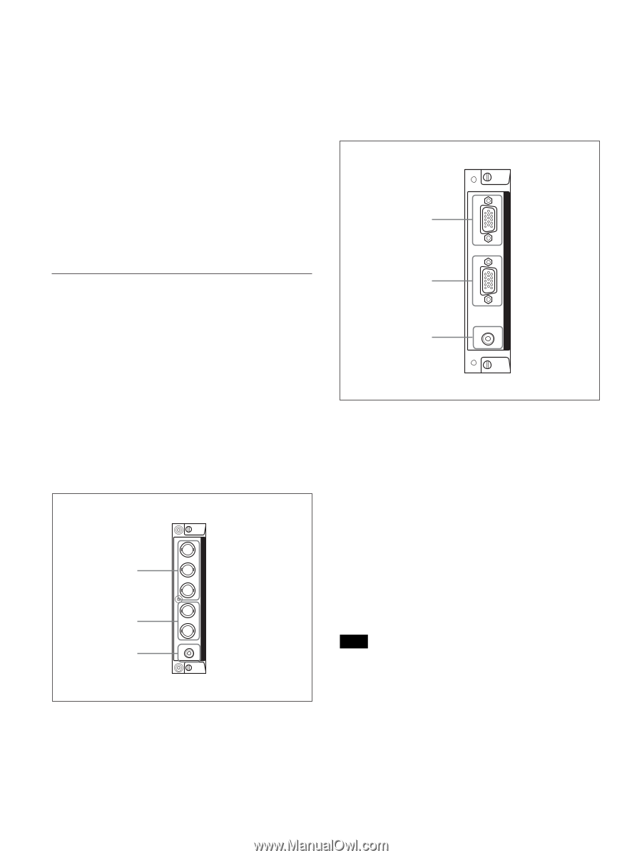
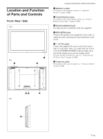
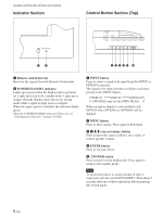
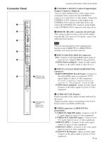
Location and Function of Parts and Controls 7 OPTION1 slot (VIDEO/COM port) This slot supports video signals and communication function. When you install an optional adaptor with communication function such as BKM-FW32 or BKM-FW50 into this slot, you can control the display unit via the network. 8 OPTION2 slot (VIDEO port) (Only for the FWD-40LX1) This slot supports video signals. A blank panel is attached to this slot for the factory setting. You can install an optional adaptor with video signal input/ output function into this slot. The optional adaptor with communication function should be installed in 7 OPTION1 slot. Optional adaptors (Not supplied) The connectors marked with 7 and 8 on the connector panel are slot-in types and can be fitted with any of the optional adaptors in the display. The OPTION2 slot is equipped only on the FWD40LX1. For details on installation, consult your Sony dealers. VIDEO/S VIDEO input/output adaptor BKMFW10 (Not supplied) This is the same as the preinstalled connectors 6. COMPONENT/RGB Input Adaptor BKM-FW11 (Not supplied) 1 2 3 1 Y/G PB/CB/B PR/CR/R IN (BNC) : Connects to the analog RGB signal or component (YUV) signal output of a piece of video equipment or a computer. 2 HD VD IN : Connects to the synchronization signal output of a computer. AUDIO VD HD PR/CR/R PB/CB/B Y/G COMPONENT/RGB INPUT ADAPTOR 3 AUDIO (Stereo minijack) : Inputs an audio signal. Connects to the audio output of a piece of video equipment or a computer. RGB/COMPONENT ACTIVE THROUGH ADAPTOR BKM-FW12 (Not supplied) 1 2 3 1 RGB/COMPONENT IN (D-sub 15-pin) : Connects to the component signal output or analog RGB signal output of a piece of video equipment or a computer. For details on inputting a component signal to the connector, see "Pin assignment" on page 44 (GB). 2 RGB/COMPONENT OUT (D-sub 15-pin) : Connects to the component signal input or analog RGB signal input of a piece of video equipment or a computer. 3 AUDIO IN (Stereo minijack) : Inputs audio signal. Connects to the audio signal output of a piece of video equipment or a computer. Note • When the unit is not connected to an AC power or is in the standby mode, no signal is output from the RGB/COMPONENT OUT. • For details on the Option Adaptors for system expansion, BKM-FW series, refer to each instruction manual. AUDIO IN OUT IN RGB/COMPONENT ACTIVE THROUGH 10 (GB)
-
 1
1 -
2
-
3
-
4
-
 5
5 -
 6
6 -
 7
7 -
 8
8 -
 9
9 -
 10
10 -
 11
11 -
 12
12 -
 13
13 -
 14
14 -
 15
15 -
16
-
17
-
18
-
19
-
20
-
21
-
22
-
23
-
24
-
25
-
26
-
27
-
28
-
29
-
30
-
31
-
32
-
33
-
34
-
35
-
36
-
37
-
38
-
39
-
40
-
41
-
42
-
43
-
44
-
45
 |
 |