Sony FWD-32LX1R Operating Instructions - Page 18
CUSTOM SETUP menu
 |
View all Sony FWD-32LX1R manuals
Add to My Manuals
Save this manual to your list of manuals |
Page 18 highlights
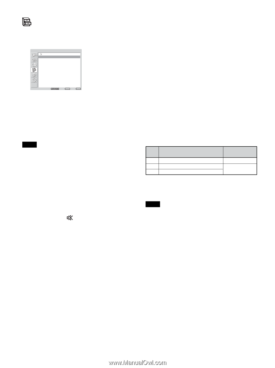
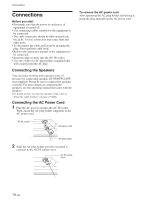
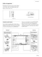
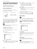
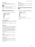
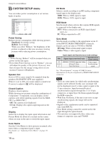
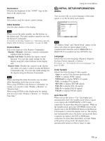
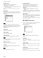
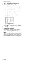
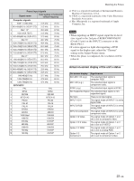
Using On-screen Menus CUSTOM SETUP menu You can reduce power consumption or set various kinds of modes. CUSTOM SETUP Power Saving: Speaker Out: Closed Caption: Display: Color Matrix HD Mode: RGB Mode Sync Mode: Illumination: Remote Standard Off Off Off 1080i H/Comp High Select Set ENTER Exit MENU Power Saving Reduces power consumption while showing pictures. Standard: No energy saving Reduce: Save energy When you select "Reduce," the brightness of the picture is reduced so that you can enjoy viewing pictures while reducing power consumption. Notes • "Power Saving: Reduce" will be resumed when you power on the unit again. • Even when Power Saving is set to "Reduce", you can still adjust the quality of the picture. However, note that you may lose the energy saving effects if you increase Contrast or Brightness. Speaker Out Set it to ON to cause sound to be emmited from the speakers SS-SP40FW/32FW (not supplied.) When it is set to Off, you cannot adjust a sound level. If you try to adjust it, will be displayed. Closed Caption Displays closed captions. While showing two pictures using the combination of Component + Component, you can display closed captions only while inputting signals from the BKMFW11 or BKM-FW12. Off: The caption is not displayed. CC1-4: Displays the caption superimposed on the picture. Display Select On to display the input signal information and Picture Mode for about five seconds on the screen when you turn on the unit or switch the input signal. Color Matrix Sets the Color Matrix to show pictures in natural color tones when a component signal is input. For details, see "Adjusting Color Matrix" on page 36 (GB). 18 (GB) HD Mode Selects a mode according to an HD analog component signal input to the display unit. 1080i: When a 1080i signal is input 1035i: When a 1035i signal is input RGB Mode Sets the mode when a device that outputs RGB signals is connected to the display unit. DTV: When connected to an RGB signal digital tuner, etc. PC: When connected to a PC. Sync Mode Sets the mode according to the signal input at pin 13 of the INPUT2 RGB/COMPONENT connector. Signals can be set only to 575/50I or 480/60I. H/Comp: When a horizontal signal is input Video: When a video signal is input PIN 13 13/14 2 Input signal and Synchronous mode settings Synchronous Signal input over the D-sub mode setting 480/60I, 575/50I Composite Video H Sync/V Sync Sync On Green Video signal Synchronizing signal See "Pin assignment" on page 44 (GB) for more information on the pin assignments of RGB/COMPONENT connector. Notes • There are some inputs for which only synchronizing signals can be selected. In this case, an image will not be displayed even if a video signal is input to the 13 pin connector. Input horizontal/vertical synchronization signals through the 13 or 14 pin connectors, or input Sync On Green signals through the RGB connector. • With Sync On Green, if the unit is not set to accept synchronizing signals, the image will not be displayed. • Signals of the synchronous mode can be supported only with INPUT2. • Sync Mode settings cannot be carried out for the input through the option boards. • This unit does not support the three value sync format of composite sync and 576/60P.
-
 1
1 -
2
-
3
-
4
-
5
-
6
-
7
-
8
-
9
-
10
-
11
-
12
-
 13
13 -
 14
14 -
 15
15 -
 16
16 -
 17
17 -
 18
18 -
 19
19 -
 20
20 -
 21
21 -
 22
22 -
 23
23 -
24
-
25
-
26
-
27
-
28
-
29
-
30
-
31
-
32
-
33
-
34
-
35
-
36
-
37
-
38
-
39
-
40
-
41
-
42
-
43
-
44
-
45
 |
 |