Sony FWD-32LX1R Operating Instructions - Page 8
Indicator Control Button Top - remote
 |
View all Sony FWD-32LX1R manuals
Add to My Manuals
Save this manual to your list of manuals |
Page 8 highlights
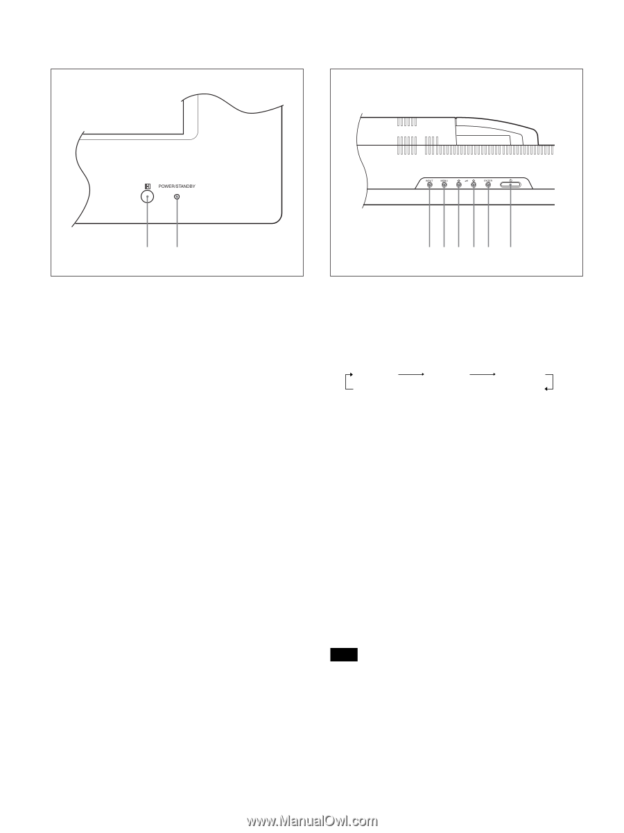
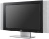
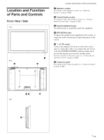
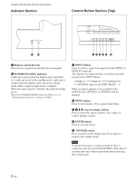
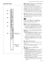
Location and Function of Parts and Controls Indicator Section Control Button Section (Top) 12 12345 6 1 Remote control detector Receives the signals from the Remote Commander. 2 POWER/STANDBY indicator Lights up in green when the display unit is powered on. Lights up in red in the standby mode. Lights up in orange when the display enters the power saving mode while a signal is input from a computer. When the input signal is switched, the indicator blinks green. When the POWER/STANDBY indicator blinks red, see "Self-diagnosis Function" on page 41 (GB). 1 INPUT button Press to select a signal to be input from the INPUT or OPTION connector. The signal to be input switches as follows each time you press the INPUT button. INPUT1 INPUT2 OPTION1 OPTION2 (only for the FWD-40LX1) When an option adaptor is not installed in the OPTION slot, OPTION1 or OPTION2 will be skipped. 2 MENU button Press to show menus. Press again to hide them. 3 4 m/M (cursor/volume) button Press to move the cursor (yellow), set a value, or control speaker volume. 5 ENTER button Press to set your choice. 6 1POWER switch Press to power on the display unit. Press again to return to the standby mode. Note To protect the panel, a certain amount of time is required to turn the unit ON/STANDBY. Wait about 5 seconds after one of these operations before pressing this switch again. 8 (GB)
-
 1
1 -
2
-
 3
3 -
 4
4 -
 5
5 -
 6
6 -
 7
7 -
 8
8 -
 9
9 -
 10
10 -
 11
11 -
 12
12 -
 13
13 -
14
-
15
-
16
-
17
-
18
-
19
-
20
-
21
-
22
-
23
-
24
-
25
-
26
-
27
-
28
-
29
-
30
-
31
-
32
-
33
-
34
-
35
-
36
-
37
-
38
-
39
-
40
-
41
-
42
-
43
-
44
-
45
 |
 |