Sony FWD-32LX1R Operating Instructions - Page 9
Connector Panel - fwd 40lx1
 |
View all Sony FWD-32LX1R manuals
Add to My Manuals
Save this manual to your list of manuals |
Page 9 highlights
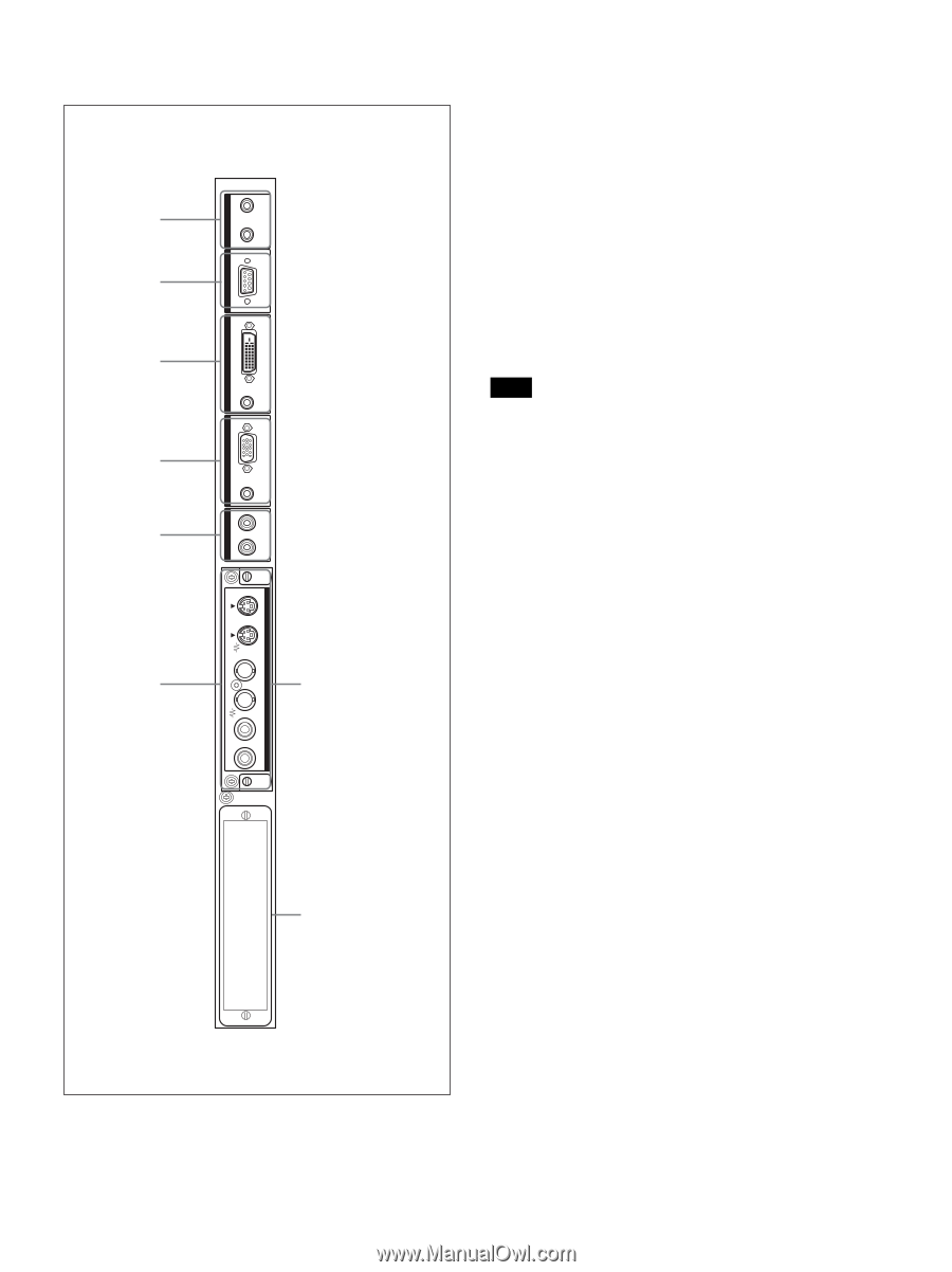
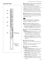
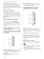
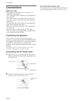
IN CONTROL S OUT REMOTE Connector Panel 1 2 3 4 5 DVI-HDCP INPUT 1 AUDIO RGB/COMPONENT INPUT 2 AUDIO L AUDIO OUT R S VIDEO IN OUT VIDEO IN 6 7 OPTION1 Slot (VIDEO/COM ) VIDEO INPUT ADAPTOR OUT AUDIO IN L R 8 OPTION2 Slot (VIDEO) (Only for the FWD-40LX1) Location and Function of Parts and Controls 1 CONTROL S IN/OUT (Control S Signal Input/ Output) Connector (Minijack) You can control multiple devices with a single remote commander when connected to the CONTROL S connector of a video device or other display. Connect the CONTROL S OUT connector on this display to the CONTROL S IN connector of the other device, and connect the CONTROL S IN connector on this display to the CONTROL S OUT connector of the other device. 2 REMOTE (RS-232C) connector (D-sub 9-pin) This connector allows remote control of the display using the RS-232C protocol. For details, contact your authorized Sony dealers. Note When an optional adaptor with communication function such as BKM-FW32 or BKM-FW50 is installed, you cannot use this connector. 3 INPUT1 (DIGITAL RGB IN) connectors DVI : Connects to the digital RGB signal output of video devices. Supports HDCP copy protection. AUDIO (Stereo minijack) : Inputs an audio signal. Connects to the audio output of video devices. 4 INPUT2 (ANALOG RGB/COMPONENT IN) connectors RGB/COMPONENT (D-sub 15-pin) : Connects to the analog RGB signal or component (YUV) signal output of a piece of video equipment. For details on inputting a component signal to the connector, see "Pin assignment" on page 44 (GB). AUDIO (Stereo minijack) : Inputs an audio signal. Connects to the audio output of a piece of video equipment. 5 AUDIO OUT L/R (Pinjack) Outputs an audio of the signal currently indicated on the screen. Outputs an audio signal corresponding to the Active Picture while in the P&P or PinP mode. 6 VIDEO connectors (A BKM-FW10 is preinstalled.) S VIDEO IN (Mini DIN 4-pin) : Connects to the Y/ C signal output of a piece of video equipment. S VIDEO OUT (Mini DIN 4-pin) : Connects to the Y/C signal input of a piece of video equipment. VIDEO IN (BNC) : Connects to the video signal output of a piece of video equipment. VIDEO OUT (BNC) : Connects to the video signal input of a piece of video equipment. AUDIO IN L/R (Pinjack) : Inputs an audio signal. Connects to the audio output of a piece of video equipment. 9 (GB)
-
 1
1 -
2
-
3
-
 4
4 -
 5
5 -
 6
6 -
 7
7 -
 8
8 -
 9
9 -
 10
10 -
 11
11 -
 12
12 -
 13
13 -
 14
14 -
15
-
16
-
17
-
18
-
19
-
20
-
21
-
22
-
23
-
24
-
25
-
26
-
27
-
28
-
29
-
30
-
31
-
32
-
33
-
34
-
35
-
36
-
37
-
38
-
39
-
40
-
41
-
42
-
43
-
44
-
45
 |
 |