Sony GVM-2000 Operating Instructions
Sony GVM-2000 Manual
 |
View all Sony GVM-2000 manuals
Add to My Manuals
Save this manual to your list of manuals |
Sony GVM-2000 manual content summary:
- Sony GVM-2000 | Operating Instructions - Page 1
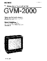
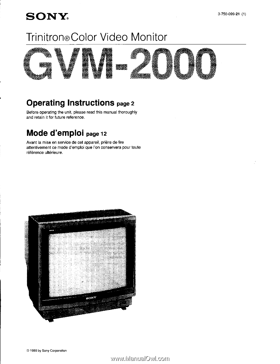
SONY® Trinitron®Color Video Monitor 3-750-099-21 (1) Operating Instructions page 2 Before operating the unit, please read this manual thoroughly and retain it for future reference. Mode d'emploi page 12 Avant la mise en service de cet appareil, priere de lire attentivement ce mode d'emploi que Ion - Sony GVM-2000 | Operating Instructions - Page 2
call upon your Sony dealer regarding this product. Model No. GVM-2000 Serial No. (servicing) instructions in Problems". This booklet is available from the U.S. Government Printing Office, Washington, DC 20402, Stock No. 004-000-00345-4. The shielded interface cable recommended in this manual - Sony GVM-2000 | Operating Instructions - Page 3
contact your authorized Sony dealer. The GVM-2000 is a high-resolution color video monitor for use with video or RGB video equipment. Monitoring RGB signals of automatically terminated at 75 ohms when no cable is connected to the output connector. When a cable is connected to the output connector, - Sony GVM-2000 | Operating Instructions - Page 4
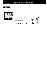
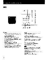
Location and Function of Parts and Controls Front panel ¶ OO 0 0000 as a O 3 r El LEI 111 9 10 Tf 12 13 4 - Sony GVM-2000 | Operating Instructions - Page 5
UP button for more volume or press the DOWN button for less volume. to Input select buttons Press to select the input source to be monitored. LINE A: for input signals fed through the LINE A connectors LINE B: for input signals fed through the LINE B connectors RGB A: for input signals fed through - Sony GVM-2000 | Operating Instructions - Page 6
outputs of video equipment such as VCRs or video disc players. For a loop-through connection, connect to the video and audio outputs of another monitor. VIDEO OUT connector(BNC type) AUDIO OUT jack(monaural)(phono type) For a loop-through connection, connect to the video and audio inputs of another - Sony GVM-2000 | Operating Instructions - Page 7
with a microcomputer, be sure to use either of the following optional connecting cables: SMF-521 (9-pin to 15-pin) SMF-522 (9-pin to 9-pin) applied to this connector, signal input from the RGB A connector will be monitored regardless of the setting of the input select buttons on the front panel. If - Sony GVM-2000 | Operating Instructions - Page 8
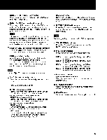
Specifications Color system NTSC system Picture tube Trinitron tube Approx. 50.6 cm (20 inches) picture measured diagonally, 100-degree deflection AG Pitch 0.55 mm (center 0.5 mm) Resolution Video inputs: 560 TV lines RGB inputs: 720 dots x 480 lines Color temperature 9300° K + 8MPCD - Sony GVM-2000 | Operating Instructions - Page 9
Pin assignment Y/C (Y/C separate) INPUT connector Pin No. 1 Y-input Signal 2 CHROMA sub-carrier-input 3 GND for Y-input 4 GND for CHROMA-input * Slot for internal switch RGB multi connector (9-pin) 1 0 2 0 3 0 4 0 0 0 0 0 0 6 789 Description 1 Vp-p, sync negative, 75 ohms 300 mVp - Sony GVM-2000 | Operating Instructions - Page 10
Timing Chart Horizontal Video Sync Video Sync Vertical A • B C DI E J fH A (µs) B (µs) C (µs) D (µs) E (µs) fV F (ms) G (ms) H (ms) I (ms) J (ms) Sync H Polarity V 0.064 1.08 12.71 0.416 14.27 + VGA compatible 31.47 kHz 3.81 1.91 25.42 0.64 31.78 70 Hz 0.064 1.87 11.13 1.206 14.27 + - 60
-
 1
1 -
 2
2 -
 3
3 -
 4
4 -
 5
5 -
 6
6 -
 7
7 -
8
-
9
-
10
 |
 |
SONY®
3-750-099-21
(1)
Trinitron®Color
Video
Monitor
Operating
Instructions
page
2
Before
operating
the
unit,
please
read
this
manual
thoroughly
and
retain
it
for
future
reference.
Mode
d'emploi
page
12
Avant
la
mise
en
service
de
cet
appareil,
priere
de
lire
attentivement
ce
mode
d'emploi
que
Ion
conservera
pour
toute
reference
ulterieure.
sornt
©
1989
by
Sony
Corporation