Sony HCD-FX80 DAVFX80 Instructions (complete HT system) - Page 21
Installing the speakers on the wall, happens, check the speaker connection again.
 |
View all Sony HCD-FX80 manuals
Add to My Manuals
Save this manual to your list of manuals |
Page 21 highlights
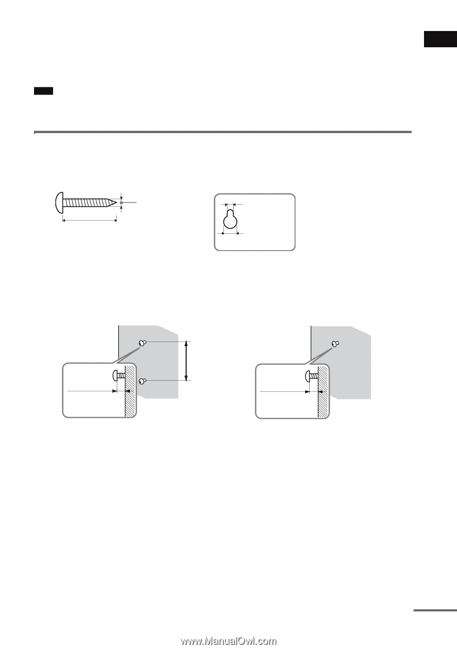
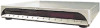
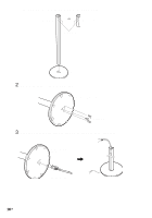
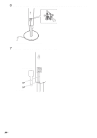
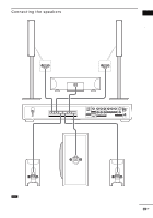
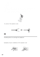
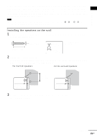
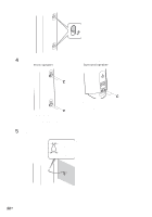
Getting Started After connecting all the components, speakers, and AC power cord (mains lead), output a test tone to check that all the speakers are connected correctly. For details on outputting a test tone, see page 83. If no sound is heard from a speaker while outputting a test tone, or a test tone is output from a speaker other than the one currently displayed on the Setup Display, the speaker may be short-circuited. If this happens, check the speaker connection again. Note • Be sure to match the speaker cord to the appropriate terminal on the components: 3 to 3, and # to #. If the cords are reversed, the sound will lack bass and may be distorted. Installing the speakers on the wall 1 Prepare screws (not supplied) that are suitable for the hole on the back of each speaker. See the illustrations below. 25 mm (1 inch) 4 mm (5/32 inch) 4.6 mm (3/16 inch) 10 mm (13/32 inch) Hole on the back of the speaker 2 Fasten the screws to the wall. The screws should protrude 7 to 8 mm (9/32 to 11/32 inch) for the front speakers, 8 to 9 mm (11/32 to 3/8 inch) for the surround speakers. For the front speakers For the surround speakers 165 mm (6 1/2 inch) 7 to 8 mm (9/32 to 11/32 inch) 8 to 9 mm (11/32 to 3/8 inch) 3 Peel the seals off the two screw points on the rear of the speaker. (Front speakers only) continued 21US
-
 1
1 -
2
-
3
-
4
-
5
-
6
-
7
-
8
-
9
-
10
-
11
-
12
-
13
-
14
-
15
-
 16
16 -
 17
17 -
 18
18 -
 19
19 -
 20
20 -
 21
21 -
 22
22 -
 23
23 -
 24
24 -
 25
25 -
 26
26 -
27
-
28
-
29
-
30
-
31
-
32
-
33
-
34
-
35
-
36
-
37
-
38
-
39
-
40
-
41
-
42
-
43
-
44
-
45
-
46
-
47
-
48
-
49
-
50
-
51
-
52
-
53
-
54
-
55
-
56
-
57
-
58
-
59
-
60
-
61
-
62
-
63
-
64
-
65
-
66
-
67
-
68
-
69
-
70
-
71
-
72
-
73
-
74
-
75
-
76
-
77
-
78
-
79
-
80
-
81
-
82
-
83
-
84
-
85
-
86
-
87
-
88
-
89
-
90
-
91
-
92
-
93
-
94
-
95
-
96
-
97
-
98
-
99
-
100
-
101
-
102
-
103
-
104
 |
 |