Sony HDCU-4300 Operation Guide
Sony HDCU-4300 Manual
 |
View all Sony HDCU-4300 manuals
Add to My Manuals
Save this manual to your list of manuals |
Sony HDCU-4300 manual content summary:
- Sony HDCU-4300 | Operation Guide - Page 1
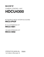
CAMERA CONTROL UNIT HDCU4300 NETWORKED MEDIA INTERFACE BOARD HKCU-IP43F ST 2110 INTERFACE KIT HKCU-4001 12G-SDI EXTENSION KIT HKCU-4002 OPERATION MANUAL [English] 1st Edition (Revised 4) - Sony HDCU-4300 | Operation Guide - Page 2
Board (Option 10 HKCU-4001 ST 2110 Interface Kit (Option 11 HKCU-4002 12G-SDI Extension Kit (Option 11 Connections and Settings 12 4K System Connection 12 HD CUTOUT Video System 13 HFR Video System 14 HDR Video System 16 Relationship between Connection Type and BNC Connector Assignment 17 - Sony HDCU-4300 | Operation Guide - Page 3
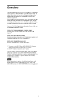
HDCU4300 Camera Control Unit connects to a HDC4300 Color Camera or HDC-P43 Multi Purpose Camera1) with an optical fiber cable, and carries out the processing of video signals from the camera and provides an interface with external equipment. Connecting a camera facilitates 4K Enables operation of - Sony HDCU-4300 | Operation Guide - Page 4
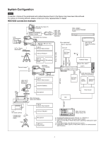
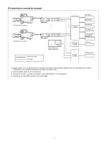
on choosing devices, please contact your Sony representative or dealer. HDC4300 connection example Lens video input Intercom NXL-FR318 Signal Processing Unit b) 4K Video Monitor < or c) m Network Switch Optical Intercom Headset LAN cable BNC BNC HDCU4300 2K Video Monitor RCP-3000/1000 - Sony HDCU-4300 | Operation Guide - Page 5
BNC Lens (for ENG/EFP) HDC-P43 Multi Purpose Camera Single-mode fiber cable (ST connectors, 1 pair) Optical fiber cable V shoe VCT-14 Tripod Attachment Tripod for portable camera USB flash drive HKCU-SM100 CCU Extension Adapter a) Dual HD-SDI video outputs HDCU4300 LAN cable Hub BNC CCA - Sony HDCU-4300 | Operation Guide - Page 6
b) HDC4300 Color Camera HDC4300 Color Camera a) c) c) d) HDCU4300 b) MSU-1000 series Master Setup Unit Optical fiber cable LAN cable IP switch × 2 10G/25G IP switch 10G/ -1 and LAN-2 connectors of the HKCU-4001 ST 2110 Interface Kit. d) Connect to the LAN-COM connector of the HDCU4300. 6 - Sony HDCU-4300 | Operation Guide - Page 7
receives a yellow tally signal. c Green tally indicator Lights in green when this unit receives a green tally signal. d CCU number display Displays the camera number set in the CCU menu. e NMI STATUS indicator or NETWORK indicator • NMI STATUS indicator (when HKCU-IP43F is installed) Displays the - Sony HDCU-4300 | Operation Guide - Page 8
headset with a plug other than an XLR 5-pin plug, consult a Sony service or sales representative. h MAIN POWER switch and indicator Turns the entire function for this button via the CCU menu. m Menu lock switch This locks out operation of the front panel menu operation area. n Call button When - Sony HDCU-4300 | Operation Guide - Page 9
connector with the supplied cap. • To connect to the HDC-P43, an HKCU-SM100 CCU Extension Adapter and a single-mode fiber cable are required. . For details on the setup menu, contact a Sony service or sales representative. Refer also to the Master Setup Unit manual. i 3G/HD SDI I/O 1/2 (SDI input/ - Sony HDCU-4300 | Operation Guide - Page 10
HDCU4300 supports IP output of a single 4K signal or dual HD signals by installing an HKCU-IP43F in the HDCU4300. HDCU4300 software version 1.11 or later is required. In addition, an OTM-10GSR1 or other SFP+ module is required to use IP output. For details about installation, contact a Sony service - Sony HDCU-4300 | Operation Guide - Page 11
should perform tasks inside the unit. The HDCU4300 supports 4K 2-system 12G-SDI output or 6G-SDI output by installing an HKCU-4002 in the HDCU4300. HDCU4300 software version 1.50 or later is required. For details about installation, contact a Sony service or sales representative. 1 a 12G/6G-SDI - Sony HDCU-4300 | Operation Guide - Page 12
from 4K signals can be output from SLOT2 and SLOT3. 1) Requires an HKCU-SM100 CCU Extension HDCU4300 HDC4300 Purpose Menu/Page Item Set value HD system format setting SYSTEM OPERATION/ BASE FORMAT Set other than 3G-SDI Video format setting SYSTEM OPERATION/ 4K - Sony HDCU-4300 | Operation Guide - Page 13
the 4K signal by installing the optional SZC-2001/2001M/2001W HD CUTOUT Software in the HDCU4300. The region that is cut out can be controlled using a mouse or other device connected to the HD CUTOUT Controller. For details about setup and operation, refer to the SZC-2001/ 2001M/2001W User's Guide - Sony HDCU-4300 | Operation Guide - Page 14
The HFR imaging function is dependent on the software version of the connected camera. Check the compatibility of each device before use. Yes: Supported, No: Not supported HDC4300, HDC-P43 (when SZC-4002 series installed on the unit) Yes Yes Yes Yes Yes Yes Yes Yes Yes Yes Yes Yes Yes Yes Yes - Sony HDCU-4300 | Operation Guide - Page 15
HD SDI Monitor For details about the assignments of BNC connectors of the unit, see "Relationship between Connection Type and BNC Connector Assignment" (page 17). HDCU4300 MSU-1000/1500 Master Setup Unit RCP-3000/1000 series Remote Control Panel 15 - Sony HDCU-4300 | Operation Guide - Page 16
CH1 CH2 PROMPTER /GEN LOCK TEST OUT SDI MONI SDI 1 SDI 2 Monitor (4K-QUAD Link) HDC4300 SDI-MONI SDI Monitor/Prompter (Digital) LINK-1 LINK-2 LINK-3 ). Settings Device HDCU4300 Purpose Transfer to HDR mode Menu/Page Item SYSTEM OPERATION/ HDR MODE SYSTEM OPERATION/ - Sony HDCU-4300 | Operation Guide - Page 17
then check the signal assignments to BNC connectors in Table 2. Table 1: Relationship between operation mode/signal format and output interface Operation mode 4K Frame rate 59.94 50 29.97 25 24 23.98 Slot1 Output format 4K/59.94P 3) Output interface Quad-Link-1 3G 1080/59.94P 4) 1080/59 - Sony HDCU-4300 | Operation Guide - Page 18
Operation mode HD HFR Frame rate 59.94(8x) 50(8x) 59.94(6x) 50(6x) 59.94 method is SQD. 2) Output only when the BASE FORMAT is 720P. 3) A Slot1 output format of "4K" refers to 4096x2160 or 3840x2160. 4) Supported when the BASE FORMAT is 1080. 5) Supported when HKCU-4002 is installed. 18 - Sony HDCU-4300 | Operation Guide - Page 19
Relationship between output interface and BNC connector assignment MAIN Output Operation mode 4K HD HFR HD CUTOUT Output interface Quad-Link-1 Dual-Link disabled, depending on the HDR MODE and COLOR SPACE settings on the HDCU4300. Disabled items can still be adjusted from the PAINT menu on the - Sony HDCU-4300 | Operation Guide - Page 20
Paint function Gamma Black Black Gamma Flare Knee Detail Shutter Skin Detail Saturation ON/OFF R/G/B/Master Step Gamma R/G/B/Master ON/OFF Range R/G/B/Master ON/OFF R/G/B/Master ON/OFF Knee Point R/G/B/Master Knee Slope R/G/B/Master Auto Knee ON/OFF Auto Knee Point Limit Auto Knee Auto Slope ON/OFF - Sony HDCU-4300 | Operation Guide - Page 21
Paint function Matrix V Mod Saw Low Key Saturation White Clip Knee Saturation Auto Iris Gamma Table Noise Suppression Flicker Reduction Black Shading White Shading Black Set OHB Matrix ATW ALAC ON/OFF User Matrix ON/OFF User Matrix R-G/G-B/B-R/R-B/G-R/B-G Multi Matrix ON/OFF Multi Matrix Phase - Sony HDCU-4300 | Operation Guide - Page 22
Paint functions that can be adjusted when COLOR SPACE is selected Paint function Gain White Gamma Black Black Gamma Flare Knee Detail Shutter Skin Detail Step Gain Master White Gain R/G/B Balance/C Temp ON/OFF R/G/B/Master Step Gamma R/G/B/Master ON/OFF Range R/G/B/Master ON/OFF R/G/B/Master ON/ - Sony HDCU-4300 | Operation Guide - Page 23
Paint function Saturation Matrix V Mod Saw Low Key Saturation White Clip Knee Saturation Auto Iris Gamma Table Noise Suppression Flicker Reduction Black Shading White Shading Black Set ON/OFF Saturation ON/OFF User Matrix ON/OFF User Matrix R-G/G-B/B-R/R-B/G-R/B-G Multi Matrix ON/OFF Multi Matrix - Sony HDCU-4300 | Operation Guide - Page 24
code, up to 32 characters Specifies the network to send trap notifications. Specifies the trap destination. SNMP walk/get from the specified trap destination is supported. Fixed value Fixed value 24 - Sony HDCU-4300 | Operation Guide - Page 25
Status Display The CCU system status can be monitored using a video monitor connected to the PIX connector. For information on monitoring and changing settings, see "Menu Settings" (page 28). - Sony HDCU-4300 | Operation Guide - Page 26
Audio Out: Output format of the AUDIO OUT connector of the unit Camera and unit intercom status *Intercom* Camera Engineer Producer CCU MIC/PGM Line :MIC On :MIC Off :MIC Off :System 04/05 Camera Engineer: Camera microphone status of the ENG line of the camera Camera - Sony HDCU-4300 | Operation Guide - Page 27
Warning display *Alarm* CCU:DVP FAN STOP CCU:NETWORK ERROR 05/05 12G/6G-SDI connector output status (when HKCU-4002 is installed) *12G/6G-SDI Status* SDI OUT STATUS: SLOT1-2 OK 06/ - Sony HDCU-4300 | Operation Guide - Page 28
the menu page, then press the CONTROL knob. The CCU MENU showing the menu configuration is displayed. ** CCU MENU ** cSYSTEM OPERATION VIDEO/MONITOR AUDIO/INTERCOM MAINTENANCE NETWORK DIAGNOSIS Menu name SYSTEM OPERATION VIDEO/MONITOR AUDIO/INTERCOM MAINTENANCE NETWORK DIAGNOSIS Description Input - Sony HDCU-4300 | Operation Guide - Page 29
To select an item in the CCU MENU Turn the CONTROL knob to move the pointer (,) up/ to exit the menu screen. The DISP/MENU lever can be set to the MENU position again to restart the operation. 3 Press the CONTROL knob. The question mark (?) changes back to the pointer (,), and the item setting is - Sony HDCU-4300 | Operation Guide - Page 30
OPERATION menu CAMERA I/F (S01) GENLOCK (S02) MULTI FORMAT (S03) HDR (S04) OUTPUT FORMAT (S05) OUTPUT FORMAT2 (S06) b) c) OUTPUT FORMAT3 (S07) c) OUTPUT LASER DIODE START UP VIDEO SIGNAL REFERENCE LOCK STATUS GENLOCK 10F BB H-PHASE STEP H-PHASE COARSE V-PHASE SYNC OUT SELECT SYSTEM BASE FORMAT 4K - Sony HDCU-4300 | Operation Guide - Page 31
MONITOR menu AUDIO/INTERCOM menu COLOR BAR (V01) BAR CHARACTER (V02) DOWNCONVERT (V03) HFR PAINT OFFSET (V04) MONITOR (V05) SPIRIT LEVEL (V06) DISPLAY (V07) 4K/HD SDR HDR MF-CB SLOPE SD SOURCE SELECT BAR-CHARACTER MOVING SYMBOL TYPE SIZE 2SI DIAMOND MARKER HFR CHANNEL MARK BAR CHARACTER CLEAR ALL - Sony HDCU-4300 | Operation Guide - Page 32
a) b) (N05) a) (N07) b) IP ADDRESS SUBNET MASK DEFAULT GATEWAY MAC ADDRESS CNS MODE MCS MODE CCU NO MASTER IP ADDRESS TSL UMD PORT PORT NUMBER PACKET STATUS NETWORK INTERFACE DHCP IP ADDRESS SUBNET MASK DEFAULT GATEWAY STATUS MULTICAST ADDRESS b) HITLESS FAILOVER b) ST 2110 4K SAP ANNOUNCE 32 - Sony HDCU-4300 | Operation Guide - Page 33
MULTICAST ADDRESS 1 b) (N08) MULTICAST ADDRESS 2 b) (N09) MULTICAST ADDRESS 3 b) (N10) MULTICAST ADDRESS 4 b) (N11) MULTICAST ADDRESS VIDEO OUT(4K) LAN1-1 IP ADDRESS PORT VIDEO OUT(4K) LAN1-2 IP ADDRESS PORT VIDEO OUT(HD) LAN1-1 IP ADDRESS PORT VIDEO OUT(HD) LAN1-2 IP ADDRESS PORT VIDEO OUT(HD) - Sony HDCU-4300 | Operation Guide - Page 34
NET a) HKCU-4001 b) FAN1 FAN2 CAM POWER SUPPLY HOUR METER MODEL NAME SERIAL NUMBER HKCU-4001 b) HKCU-IP43F a) APPLICATION OS UPDATER MIF VIF TX SY 4K-POST SDP DEC(HDC4300) DPR(NORMAL) DPR(HCO) DPR(Sub) NET a) NMI LSI a) NET1 b) NET2 b) NAME ROM VERSION POWER(NET) POWER(CN) NMI1 SFP+ MODULE - Sony HDCU-4300 | Operation Guide - Page 35
CANCEL/ENTER lever to the ENTER position to execute. SYSTEM OPERATION menu SYSTEM OPERATION Page name Page No. S01 S02 with the camera. ON, OFF Turns the optical signal output from the CCU to the camera ON/OFF. (Displayed only when connected using optical fiber composite - Sony HDCU-4300 | Operation Guide - Page 36
/50I, 1080/25PsF, 1080/24PsF, 720/50P See "4K/HFR FORMAT" (page 41). Sets the 4K/HD HFR operation format based on the BASE FORMAT setting. WIDE-F, WIDE-BC 709 color gamut output and BT.2020 color gamut output operation. It also supports all camera paint functions. S04 FRAME CONVERT DELAY - Sony HDCU-4300 | Operation Guide - Page 37
SYSTEM OPERATION Page name Page output. BT.709: 709 color space setting close to HDC-series cameras. BT.2020: Applicable for color space selected connector output format when (when HKCU-4002 is installed)" SLOT1-1 is set to 4K format. (page 43). C, M See "Formats settable for SLOT2 and SLOT3" - Sony HDCU-4300 | Operation Guide - Page 38
SYSTEM OPERATION Page name Page No. S06 (When HKCU-IP43F or HKCU-4001 is installed) Item SLOT4(NMI) 1 2 IP OUT(4K) 1 to the output signal (fixed) When the SLOT1-1 connector output signal is a 4K video, the same video is output as an ST 2110 video stream. Displays - Sony HDCU-4300 | Operation Guide - Page 39
SYSTEM OPERATION Page ) Sets the format of the input signal selected using INPUT. For the supported formats that can be selected for each BASE FORMAT setting, see "Formats the HD matrix to the SD return signal. CHU MODE HDC4300/HDC-P43, HDC(HD CUTOUT) Sets the camera head to connect. The unit - Sony HDCU-4300 | Operation Guide - Page 40
SYSTEM OPERATION Page ON/OFF. Enabled only when HDC(HD CUTOUT) is selected in CHU MODE. The cutout HD signal from the 4K source is output from SLOT1. HD: Outputs a 1920x1080 HD region cutout from the 4K video as-is. Dual output is supported. The cutout signal set by the CUTOUT POSITION CH1 setting - Sony HDCU-4300 | Operation Guide - Page 41
/29.97PsF 1080/23.98PsF 720/59.94P 1080/50P 1080/50I 1080/25PsF 1080/24PsF 720/50P 4K/HFR FORMAT selection options When CHU MODE is HDC4300/HDC-P43 When CHU MODE is HDC(HD CUTOUT) 4096x2160/59.94P, 1080/59.94P, 1080/59.94P(2x), 1080/59.94P(3x), 4096x2160/59 - Sony HDCU-4300 | Operation Guide - Page 42
4K/HFR FORMAT settings 1080/59.94P(3x) 1080/59.94P(4x) 1080/59.94I(6x) 1080/59.94I(8x /50P(4x)/3G-A 1080/50P(4x)/3G-B 1080/50I(4x)/3G-B 1080/50I(4x) 1080/50I(6x)/3G-B 42 When CHU MODE is HDC(HD CUTOUT) - - z When BASE FORMAT is 1080/50P or 1080/50I 1080/50P/3G-A 1080/50P/3G-B 1080/50I z When BASE - Sony HDCU-4300 | Operation Guide - Page 43
4K/HFR FORMAT settings 1080/50I(8x) 720/50P 720/50P(2x) 720/50P(3x) 720/50P(4x) 720/50P(6x) 720/50P(8x) SLOT1 selection options When CHU MODE is HDC4300/HDC /25P/6G 4096x2160/24P/6G 3840x2160/24P/6G SLOT1-2 output not supported Formats settable for SLOT2 and SLOT3 BASE FORMAT settings 1080/59.94P - Sony HDCU-4300 | Operation Guide - Page 44
settings SLOT4(NMI) selection options 1) When CHU MODE is HDC4300/HDC-P43 3840x2160/50P/2SI/3G-A, 1080/50I 1080/50I SLOT4 output not supported When CHU MODE is HDC(HD CUTOUT) - 1080/50I SLOT4 output not supported 1) If SLOT4-1 is set to 4K, SLOT4-2 is unavailable. If SLOT4-1 is set to HD, SLOT4 - Sony HDCU-4300 | Operation Guide - Page 45
* OETF is SDR (fixed). IP OUT(4K)-1 --IP OUT-1, IP OUT-2 1080/50I IP OUT-3 1080/50I * OETF is SDR (fixed). IP OUT(4K)-1 3840x2160/59.94P * 4K output OETF is same as SLOT1 OETF. IP OUT-1, IP OUT-2, IP OUT-3 --IP output not supported IP OUT(4K)-1 3840x2160/50P IP OUT-1, IP OUT-2, IP - Sony HDCU-4300 | Operation Guide - Page 46
(PsF), PAL 1) Level A and Level B of 3G-SDI are detected automatically. IP RET1, IP RET2 1080/59.94P, 1080/59.94I(PsF) - (IP RET not supported) - (IP RET not supported) - (IP RET not supported) 1080/50P, 1080/50I(PsF) - (IP RET not - Sony HDCU-4300 | Operation Guide - Page 47
BAR, SD BAR Selects the color bar signal source for output to SD. 4K/HD BAR: Down converts the 4K/HD color bars and then outputs it. SD BAR: Outputs the SD color bars selected in SELECT. SYSTEM OPERATION menu t page t When 1.001(525) is selected for SYSTEM: SMPTE, EIA, FULL - Sony HDCU-4300 | Operation Guide - Page 48
value OFF, ON V02 BAR CHARACTER CLEAR ALL V03 4K-HD DOWNCONVERT FILTER SD ASPECT V04 NTSC SETUP DETAIL LEVEL for BAR CHARACTER. Selects the type of filter for downconverting from 4K video signals to HD signals. Selects the aspect for SD output. - Sony HDCU-4300 | Operation Guide - Page 49
can be set when connected with a camera which has a lens that supports serial communication attached. Selects the indicator move direction for tilting. Spirit (vertical) Sets the display of messages for the camera auto setup operation status, warnings that occur in the system, etc. ALL: Displays - Sony HDCU-4300 | Operation Guide - Page 50
like the following in the area at the bottom right of the 4K color bar during 4K 2 sample interleave output. OK is displayed if the connections for input from the MIC OUT connector of the CCU. AES/EBU: Outputs the camera AES/EBU input from the MIC OUT connector of the CCU. -20, 0, +4 dBu Sets the - Sony HDCU-4300 | Operation Guide - Page 51
/PGM switch position (Display only) Front panel INTERCOM operation status (Display only) Operation when the INTERCOM switch on the front panel is set to the PRIV position. ENABLE: Private operation DISABLE(SET TO ENG): Same function as ENG position. DISABLE( - Sony HDCU-4300 | Operation Guide - Page 52
AUDIO/INTERCOM Page name Page No. A05 (When HKCU-4001 is installed) A06 (When HKCU-4001 is installed) Item AUDIO OUT FORMAT CH ORDER PGM IN FORMAT CH ORDER INTERCOM OUT FORMAT CH ORDER INTERCOM IN FORMAT CH ORDER Set value CLEAR COM, 4WIRE, RTS L24/48kHz/1ms/2ch, L24/48kHz - Sony HDCU-4300 | Operation Guide - Page 53
: Set to VBS (CHARACTER superimposition) output. SYNC: Set to SYNC OUT output. Displayed only when a D-sub 50-pin board is installed. Sets the operation mode of REAR PREVIEW connector output. Sets the number of channels to be used. Sets the communication line mode. Sets the number of prompter lines - Sony HDCU-4300 | Operation Guide - Page 54
counterclockwise rotation selects the next data option. Displays the camera menu. Notes • If CAM MENU is set to ON, CCU menu operations cannot be performed because only camera menu operations are available. • The camera menu is not displayed when SD signal is output. Sets the date and time. Sets - Sony HDCU-4300 | Operation Guide - Page 55
to LEGACY mode. LASER DIODE ON: Turns the optical signal output from the CCU to the camera ON/OFF. Reads the installation key from the USB flash state of the LASER DIODE setting on the page of the SYSTEM OPERATION menu for the next startup. Sets the VF return signal to the camera. NORMAL - Sony HDCU-4300 | Operation Guide - Page 56
HKCU-4001 for setting the IP address. DHCP IP ADDRESS SUBNET MASK OFF 0.0.0.0 to 255.255.255.255 0.0.0.0 to 255.255.255.255 Sets DHCP operation. Fixed to OFF in the current version. Sets the IP address. Sets the subnet mask. DEFAULT GATEWAY 0.0.0.0 to 255.255.255.255 MAC ADDRESS 00 - Sony HDCU-4300 | Operation Guide - Page 57
network genlock for the selected port. Displays the supported profile. Only ST2059-2 profile is supported. Sets the domain number. Note Set to TWO-STEP: Sent in Follow-up message. Displays the PTP operation status. NOT IN USE: PTP operation stopped NO MASTER: PTP master is not found. LOCKING: - Sony HDCU-4300 | Operation Guide - Page 58
option is fixed to MANUAL, and the multicast addresses are set manually on the MULTICAST ADDRESS 1 to 5 pages. HITLESS FAILOVER ON, OFF Sets whether to use IP stream redundancy. (When HKCU-4001 is installed) ON: Use redundancy. OFF: Do not use redundancy. ST 2110 4K ENABLE, DISABLE Enables - Sony HDCU-4300 | Operation Guide - Page 59
ADDRESS PORT AUDIO OUT LAN2 PGM IN LAN1 IP ADDRESS PORT SRC IP PGM IN LAN2 AUTO, MANUAL Displays the mode of the multicast address setting of the IP stream. Settings for the IP 4K OUT1 output video signal 224.0.0.1 to 239.255.255.255, 0.0.0.0 Sets the transmit destination multicast IP address - Sony HDCU-4300 | Operation Guide - Page 60
ADDRESS PORT SRC IP INTERCOM IN LAN2 MULTICAST ADDRESS META OUT LAN1-1 AUTO, MANUAL 224.0.0.1 to 239.255.255.255, 0.0.0.0 100 to 65535, 30000 Same as 65535, 30000 0.0.0.0 to 255.255.255.255 Same as INTERCOM IN LAN1 AUTO, MANUAL IP ADDRESS PORT META OUT LAN1-2 224.0.0.1 to 239.255.255.255, 0.0.0.0 - Sony HDCU-4300 | Operation Guide - Page 61
board self-diagnosis result OK, STOP Power supply unit fan operation status OK, STOP Fan operation status ON, OFF Status of power supply to camera Accumulated PLD (TX board) ROM version of SY PLD (SY board) ROM version of 4K-POST PLD (DVP board) ROM version of SPD PLD (DVP board) ROM version - Sony HDCU-4300 | Operation Guide - Page 62
DIAGNOSIS Page name Page No. Item D06 (When HKCU-IP43F is installed) POWER(NET) POWER(CN) NMI1 SFP+ MODULE TX RX NMI2 SFP+ MODULE TX RX D06 (When HKCU-4001 is installed) BOARD S/N IF FAN1 FAN2 NET NET1 NET2 BOARD S/N Display OK, ABSENT OK, - Sony HDCU-4300 | Operation Guide - Page 63
your Sony representative. The life expectancy of the electrolytic capacitor is about 5 years under normal operating CCU:XXX TEMP WARNING Board temperature error (XXX is the board name) CCU:OPT NO OPTION Option key required for when CHU MODE is set to HDC(HD CUTOUT) is not installed. CCU - Sony HDCU-4300 | Operation Guide - Page 64
Specifications HDCU4300 General Power requirements 100 V to 240 V AC, 50/60 Hz Current consumption 4.0 A (max.) Operating temperature 5 °C to 40 °C (41 °F to 104 °F) Storage temperature -20 °C to +60 °C (-4 °F to +140 °F) Mass Approx. 10.1 kg (22 lb 4.3 oz) Dimensions (Unit: mm (inches)) - Sony HDCU-4300 | Operation Guide - Page 65
), contact your Sony sales or service representative. Supplied accessories Flat cable 30-pin (1) Coaxial cable 30-pin (1) Coaxial cable 40-pin (1) Power supply harness (1) Screws M3×8 (6) Screws M2.6×5 (2) Wire saddle (4) Protective tape (1) Label (1) Operating Instructions (1) Related - Sony HDCU-4300 | Operation Guide - Page 66
12G-SDI/6G-SDI switchable Supplied accessories 40-pin cable (1) Harness (2) Operating Instructions (1) Design and specifications are subject to change without notice. Notes • Always verify that the unit is operating properly before use. SONY WILL NOT BE LIABLE FOR DAMAGES OF ANY KIND INCLUDING - Sony HDCU-4300 | Operation Guide - Page 67
HDCU4300 (SY) 4-589-990-15 (2) Sony Corporation © 2016
-
 1
1 -
 2
2 -
 3
3 -
 4
4 -
 5
5 -
 6
6 -
 7
7 -
8
-
9
-
10
-
11
-
12
-
13
-
14
-
15
-
16
-
17
-
18
-
19
-
20
-
21
-
22
-
23
-
24
-
25
-
26
-
27
-
28
-
29
-
30
-
31
-
32
-
33
-
34
-
35
-
36
-
37
-
38
-
39
-
40
-
41
-
42
-
43
-
44
-
45
-
46
-
47
-
48
-
49
-
50
-
51
-
52
-
53
-
54
-
55
-
56
-
57
-
58
-
59
-
60
-
61
-
62
-
63
-
64
-
65
-
66
-
67
 |
 |

OPERATION MANUAL
[English]
1st Edition (Revised 4)
CAMERA CONTROL UNIT
HDCU4300
NETWORKED MEDIA INTERFACE BOARD
HKCU-IP43F
ST 2110 INTERFACE KIT
HKCU-4001
12G-SDI EXTENSION KIT
HKCU-4002