Sony HDRC-4000 Operation Guide
Sony HDRC-4000 Manual
 |
View all Sony HDRC-4000 manuals
Add to My Manuals
Save this manual to your list of manuals |
Sony HDRC-4000 manual content summary:
- Sony HDRC-4000 | Operation Guide - Page 1
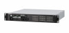
HDR PRODUCTION CONVERTER UNIT HDRC-4000 OPERATION MANUAL [English] 1st Edition (Revised 4) - Sony HDRC-4000 | Operation Guide - Page 2
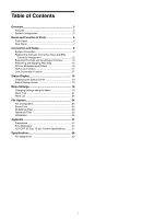
of Parts 6 Front Panel 6 Rear Panel 7 Connection and Setup 8 System Connection 8 Relationship between Connection Type and BNC Connector Assignment 12 Supported Formats and Input/Output Interface 13 Preserving and Mapping ANC Data 14 SR Live Metadata Input/Output 16 HDR Look Function 17 - Sony HDRC-4000 | Operation Guide - Page 3
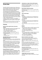
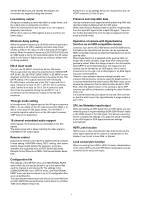
HDRC-4000 HDR Production Converter Unit converts HDR video signals using the OETF standard. OETF supports several standards, including Sony's original S-Log3 curve, SMPTE ST 2084 (PQ) and ITU-R BT. 2100 (HLG), and supports Inputs Channel A • 4K: Single-Link 12G-SDI, Quad-Link 3G-SDI/Single-Link 6G - Sony HDRC-4000 | Operation Guide - Page 4
3G/HD-SDI Multi-Link and 12G/6G-SDI Single-Link conversion are supported using this function. Low-latency output matching the video signal is embedded in the output signal. Remote control Supports the remote control by Sony system camera products. Format setting, HDR/SDR setting, OETF setting, color - Sony HDRC-4000 | Operation Guide - Page 5
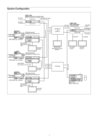
HDR Production Converter Unit Channel A 4K-HDR (S-Log3) HD-SDR Channel B BPU4000/4500A Baseband Processor Unit HDC4300 Color Camera SDI Router or Switcher HDRC-4000 HDR Production 4K-HDR Converter Unit (S-Log3) Channel A Channel B HD-SDR 4K-HDR (HLG) HD-SDR 4K-SDR 4K-SDR HDCU2000 HD Camera - Sony HDRC-4000 | Operation Guide - Page 6
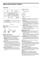
Name and Function of Parts Front Panel a b cd POWER CALL CALL RCP/MSU RCP/MSU INPUT CH A INPUT CH B CONFIGURATION 4K HD HDR 2020 A B IN 2SI HDR 2020 HDR 2020 4K OUT HD OUT MENU DISP CANCEL MENU ENTER REF IN UNLOCK COM ERROR FAN STOP MENU LOCK OFF ON NETWORK e f gh USB - Sony HDRC-4000 | Operation Guide - Page 7
peripheral device wiring that might have excessive voltage to this port. Follow the instructions for this port. • When you connect the LAN cable of the d HD INPUT CH-A, CH-B connectors Supports 3G/HD-SDI signal inputs (HD). e 4K INPUT CH-A, CH-B connectors Supports 12G/6G-SDI Single-Link or 3G/HD- - Sony HDRC-4000 | Operation Guide - Page 8
-SDI×4 outputs 4K INPUT Link-1 Link-2 Link-3 Link-4 Channel B 4K input 14K Single-Link, 4K DualLink, or 4K Quad-Link input 23G/HD-SDI×4 inputsa) HDRC-4000 Link-1 Link-2 Link-3 Link-4 4K OUT 1 4K OUT 3 4K OUT 5 4K OUT 7 I/O HD OUT Channel B HD main output (3G/HD-SDI) Channel B HD monitor output - Sony HDRC-4000 | Operation Guide - Page 9
setting Selects channel A input signal Displays the input signal auto sensing result Selects 4K input signal format ("---" is displayed for HD input or 12G/6G-SDI input) Selects OETF for the monitor to display the input signal Selects input signal color space Selects channel A 4K output connector - Sony HDRC-4000 | Operation Guide - Page 10
channel B input signal c) (HD-SDI / 3G(Lv-B) / 3G(Lv-A) / 6G-SDI / 12G-SDI) Displays the input signal auto sensing result (AUTO / 2SI / SQD) OETF b) c) Selects color space (HD-SDI / 3G(Lv-B) / 3G(Lv-A) / 6G-SDI / 12G-SDI) Selects channel B 4K output connector signal format (2SI / SQD) OETF - Sony HDRC-4000 | Operation Guide - Page 11
) 4K INPUT Link-1 Link-2 Link-3 Link-4 Channel B 4K input (3G/HD-SDI × 4ch) Link-1 Link-2 Link-3 Link-4 4K OUT 1 4K OUT 3 4K OUT 5 4K OUT 7 HDRC-4000 HD OUT Channel B HD main output (3G/HD-SDI) Channel B HD monitor output (HD-SDI) Link-1 Link-2 Link-3 Link-4 4K OUT 1 4K OUT 3 4K OUT - Sony HDRC-4000 | Operation Guide - Page 12
2 and 3. Table 1: Relationship between 4K operation mode/signal format and input/output interface System format 4K input/output interface Frequency Frame rate 1.001 59.94 12G-SDI Single-Link 3G-SDI Quad-Link 29.97 6G-SDI Single-Link 3G-SDI Dual-Link HD-SDI Quad-Link 23.98 6G-SDI - Sony HDRC-4000 | Operation Guide - Page 13
Supported Formats and Input/Output Interface 4K input/output connectors 4K input/output .98P 2160/23.98PsF 2160/50P 25 2160/25P 2160/25PsF 24 2160/24P 2160/24PsF Input/output interface 12G-SDI No division 3G-SDI Level-A/B 2SI SQD 6G-SDI No division 3G-SDI Level-B 2SI 3G-SDI - Sony HDRC-4000 | Operation Guide - Page 14
000 29.97 23.98 50 25 24 * Frame rate conversion is not supported. HD input Input format 1080/59.94P 1080/59.94i 1080/29.97PsF 1080/24PsF HD-SDI HD-SDI Preserving and Mapping ANC Data The unit supports various conversions while preserving ANC data (Ancillary Data) multiplexed with the SDI - Sony HDRC-4000 | Operation Guide - Page 15
Normal mode In this mode, when converting between HD-SDI and 3G-SDI Level-A/6G-SDI/12G-SDI (referred to as 3G-SDI Level-A), the VANC data for 3G-SDI Level-A always uses the same space, regardless of whether the HD-SDI - Sony HDRC-4000 | Operation Guide - Page 16
Field mode In this mode, when converting between HD-SDI and 3G-SDI Level-A, the space used for VANC data for 3G-SDI Level-A changes depending on whether the HD-SDI field is field 1 or field 2. When converting from HD-SDI to 3G-SDI Level-A, VANC is mapped as shown in the following figure. HD-SDI - Sony HDRC-4000 | Operation Guide - Page 17
point of the HDR Knee function [absolute value] Slope of the line above the knee point of the HDR Knee function [absolute value] 1) Only HDRC-4000 supported items are shown. 2) SR AIR OFF = Scene Referred conversion, AIR MATCHING is OFF SR AIR ON = Scene Referred conversion, AIR MATCHING is ON DR - Sony HDRC-4000 | Operation Guide - Page 18
(When the Look conversion function is ON, the HDR Black Compression item and HDR Look item are set to "---" on the Channel A/B Settings page of the CONFIGURATION menu.) For example, if you want to convert a Natural Look HLG signal to an S-Log3 signal with black level the same as SDR using Live Look - Sony HDRC-4000 | Operation Guide - Page 19
Status Display Menu Settings The unit and system status can be monitored using text characters superimposed on the HD monitor output signal. For details about checking and changing settings, see "Menu Settings" (page 19). Displaying the Status Screen The menu screen is controlled using the knob - Sony HDRC-4000 | Operation Guide - Page 20
Menu Description CONFIGURATION Use to set basic settings of the unit (excludes image quality settings). SETUP Use to set the image quality when converting video on the unit. 1. HDRtHDR Configure settings for converting from HDR to HDR. 2. HDRtSDR Configure settings for converting from HDR to - Sony HDRC-4000 | Operation Guide - Page 21
To cancel all settings Move the , cursor to ESC and push the control knob. The * (asterisk) changes back to ,, and all the changes for the item are discarded. To exit the menu In menu display mode, set the DISP/MENU lever to MENU. Menu Tree CONFIGURATION menu SYSTEM (C01) GENLOCK (C02) CHANNEL A - Sony HDRC-4000 | Operation Guide - Page 22
(C13) DATE/TIME FILE TIMESTAMP FORMAT TEMP WARNING PLD NG REFERENCE UNLOCK FAN STOP POWER SUPPLY UNIT VANC REMAPPING MODE HD-SDI/3G-B 3G-A/6G/12G CH.A STATUS APPLY ONCE APPLY CONTINUOUSLY CH.B STATUS APPLY ONCE APPLY CONTINUOUSLY CH.A 1st F 2nd F CH.B 1st F 2nd F BARS CH.A CH.B SDR BARS TYPE HDR - Sony HDRC-4000 | Operation Guide - Page 23
GAMMA (S25) WHITE CLIP (S26) SDRtHDR BLACK LEVEL (S31) SDRtHDR GAIN (S32) DE-GAMMA (S33) HIGHLIGHT CREATION (S34) HDR BLACK CLIP (S35) CHANNEL A GAMMA TABLE STEP LEVEL CHANNEL B GAMMA TABLE STEP LEVEL ABS CHANNEL A WHITE CLIP LEVEL CHANNEL B WHITE CLIP LEVEL ABS CHANNEL A SETTING MODE MASTER BLACK - Sony HDRC-4000 | Operation Guide - Page 24
ADDITIONAL PAINT menu ADDITIONAL PAINT (A01) WHITE BALANCE (A02) GAIN (A03) DETAIL (A04) SATURATION (A05) LOOK CONVERSION CHANNEL A (A06) LOOK CONVERSION CHANNEL B (A07) CHANNEL A ADDITIONAL PAINT CHANNEL B ADDITIONAL PAINT CHANNEL A WHITE BALANCE R B CHANNEL B WHITE BALANCE R B CHANNEL A GAIN - Sony HDRC-4000 | Operation Guide - Page 25
DIAGNOSIS menu BOARD STATUS (D01) ROM VERSION (D02) SERIAL NO. (D03) IP ADDRESS (D04) LAN STATUS (D05) CNS STATUS (D06) POWER SUPPLY UNIT (D07) 12G/6G-SDI STATUS (D08) SY DVP SDI DCP1 DCP2 APP OS UPDATER SY SDI DEC DCP1 DCP2 4K-POST 2K-POST SDP MODEL NO IP - Sony HDRC-4000 | Operation Guide - Page 26
Menu List Legend The following conventions are used in the menu tables. Settings ON, OFF, 0, etc.: Factory default settings shown underlined. ENTER to execute: Execute by pushing the control knob or setting the CANCEL/ENTER lever to the ENTER position. CONFIGURATION menu Use to set basic settings - Sony HDRC-4000 | Operation Guide - Page 27
inputs HD-SDI, 3G(Lv-B), 3G(Lv-A), 6G-SDI, 12G-SDI Input signal format (display only) SQD, 2SI, AUTO 4K input signal transport format setting ("---" is displayed for HD input or 12G/6G-SDI input) SQD: Square Division (quadrants) 2SI: 2-Sample Interleave AUTO: - Sony HDRC-4000 | Operation Guide - Page 28
, ON 4K, HD, HDx4IN, CH.A HD-SDI, 3G(Lv-B), 3G(Lv-A), 6G-SDI, 12G-SDI SQD, 2SI, AUTO SDR, S-Log3(Live HDR), HLG(Var1.2), PQ(ST2084), RGB(SG1.2), .709, BT.2020 Live, Mild, Natural HD-SDI, 3G(Lv-B), 3G(Lv-A), 6G-SDI, 12G-SDI SQD, 2SI SDR, S-Log3(Live HDR), HLG(Var1.2), PQ(ST2084), RGB(SG1.2), *S-Log3 - Sony HDRC-4000 | Operation Guide - Page 29
Page name Page No. C04 C05 C06 Item Set value Meaning OUTPUT HD 3G(Lv-B), 3G(Lv-A), HD-SDI HD output signal format setting HD IN B-1, HD IN B-2, HD IN B-3, When using HD×4 inputs, select the signal for HD IN B-4 output on the HD output - Sony HDRC-4000 | Operation Guide - Page 30
Page name Page No. C07 C08 C09 Item CHANNEL A MODE Set value MOTION DETECTION, FIELD COMBINATION(Weave), FIELD EXTENSION(Bob), PsF CONVERSION MOTION THRESHOLD LOW, MID, HIGH CHANNEL B MODE MOTION DETECTION, FIELD COMBINATION(Weave), FIELD - Sony HDRC-4000 | Operation Guide - Page 31
FIELD C11 HD-SDI/3G-B 3G-A/6G/12G CH.A STATUS APPLY ONCE NOT DETECTED, DETECTED APPLY CONTINUOUSLY CH.B STATUS display only) Line number of the VANC space in 3G-SDI Level-A/6G-SDI/12G-SDI signals (display only) Displays whether SR Live Metadata was detected in the - Sony HDRC-4000 | Operation Guide - Page 32
Page name Page No. C13 Item Set value Meaning BARS CH.A OFF, ON Color bar output on/off setting CH.B OFF, ON SDR BARS TYPE SDR-LOOK BAR(100%), SDR-LOOK BAR(75%), SMPTE 16:9(BLACK), SMPTE 16:9(-I/Q), BAR 4:3(100%), BAR 4:3(75%), SMPTE 4:3(BLACK), SMPTE 4:3(-I/Q), MF-ARIB(75%), MF- - Sony HDRC-4000 | Operation Guide - Page 33
to execute Meaning Select whether the source of the input video signal is a Sony made system camera or not Set the master black value of the input video signal to OTHERS) Select whether the source of the input video signal is a Sony made system camera or not Set the master black value of the input video - Sony HDRC-4000 | Operation Guide - Page 34
Page name Page No. S12 Item Set value CHANNEL A HDR BLACK CLIP OFF, ON CHANNEL B HDR BLACK CLIP OFF, ON Meaning HDR Black Clip (clipping of HDR output below 0 IRE) on/off setting. However, when the output OETF is set to SLog3(Live HDR) or S-Log3(HDR), HDR BLACK CLIP is always - Sony HDRC-4000 | Operation Guide - Page 35
to execute Meaning Select whether the source of the input video signal is a Sony made system camera or not Set the master black value of the input video signal to OTHERS) Select whether the source of the input video signal is a Sony made system camera or not Set the master black value of the input video - Sony HDRC-4000 | Operation Guide - Page 36
Page name Page No. S22 S23 Item Set value CHANNEL A HDRtSDR GAIN 0.0dB to -15.0dB, -6.0dB HDR CONTRAST CHANNEL B HDRtSDR GAIN HDR CONTRAST 0.0dB to -15.0dB, -6.0dB CHANNEL A HDR DE-KNEE OFF, ON POINT -99 to 99, 0 SLOPE -99 to 99, 0 CHANNEL B HDR DE-KNEE - Sony HDRC-4000 | Operation Guide - Page 37
Page name Page No. S24 Item CHANNEL A KNEE POINT: SLOPE: MAX Set value OFF, ON R: -99 to 99, 0 G: -99 to 99, 0 B: -99 to 99, 0 M: -99 to 99, 0 R: -99 to 99, 0 G: -99 to 99, 0 B: -99 to 99, 0 M: -99 to 99, 0 OFF, ON KNEE SATURATION CHANNEL B KNEE POINT: SLOPE: MAX OFF, ON -99 to 99, 0 OFF, - Sony HDRC-4000 | Operation Guide - Page 38
Page name Page No. S25 S26 Item CHANNEL A GAMMA TABLE STEP LEVEL R G B M CHANNEL B GAMMA TABLE STEP ABS LEVEL R G B M CHANNEL A WHITE CLIP LEVEL CHANNEL B WHITE CLIP ABS LEVEL Set value Meaning OFF, ON STANDARD, HYPER 1 to 7, 5 1 to 4 0.90, 0.85, 0.80, 0.75, 0.70, 0. - Sony HDRC-4000 | Operation Guide - Page 39
video signal source Fixed to absolute value of 0.0 when DISPLAY REFERRED on the page is ON (Displayed only when SETTING MODE is set to SONY SYSTEM CAMERA) Difference in black level between input SDR signal and output HDR signal Fixed to 0.0 when DISPLAY REFERRED on the page is ON - Sony HDRC-4000 | Operation Guide - Page 40
video signal source Fixed to absolute value of 0.0 when DISPLAY REFERRED on the page is ON (Displayed only when SETTING MODE is set to SONY SYSTEM CAMERA) Difference in black level between input SDR signal and output HDR signal Fixed to 0.0 when DISPLAY REFERRED on the page is ON - Sony HDRC-4000 | Operation Guide - Page 41
Page name Page No. S33 S34 Item CHANNEL A DE-GAMMA CHANNEL B DE-GAMMA CHANNEL A HIGHLIGHT CREATION Set value STANDARD, HYPER 1 to 7, 5 1 to 4 STANDARD, HYPER 1 to 7, 5 1 to 4 OFF, ON S35 POINT SLOPE CHANNEL B HIGHLIGHT CREATION 70.0% to 100.0%, - Sony HDRC-4000 | Operation Guide - Page 42
to execute MODE OUTPUT BLACK -99.9 to 99.9, 3.0 LEVEL (SDR) ABS ENTER to execute Meaning Select whether the source of the input video signal is a Sony made system camera or not Set the master black value of the input video signal source Fixed to absolute value of 0.0 when DISPLAY REFERRED on - Sony HDRC-4000 | Operation Guide - Page 43
Page name Page No. S42 S43 Item CHANNEL A DE-GAMMA Set value STANDARD, HYPER CHANNEL B DE-GAMMA 1 to 7, 5 1 to 4 STANDARD, HYPER CHANNEL A GAMMA TABLE 1 to 7, 5 1 to 4 OFF, ON STANDARD, HYPER CHANNEL B GAMMA TABLE 1 to 7 1 to 4 OFF, ON STANDARD, HYPER 1 to 7 1 to 4 - Sony HDRC-4000 | Operation Guide - Page 44
4KtHD Configure settings for down-converting from 4K to HD. Page name Page No. S51 Item DETAIL Set value CH. A: OFF, ON CH. B: OFF, ON HD DETAIL CH. A: OFF, ON CH. B: OFF, ON LEVEL LIMITER CRISP H/V FREQ CH. A: -99 to 99, 0 CH. B: -99 to 99, 0 CH. A: -99 to 99, 0 CH. B: -99 to 99, - Sony HDRC-4000 | Operation Guide - Page 45
Page name Page No. S53 Item SKIN DTL Set value OFF, ON SKIN GATE OFF, 1, 2, 3 NATURAL SKINDTL OFF, ON CH SW PHASE WIDTH SAT LEVEL Y LIMIT OFF, ON 0 to 359 0 to 90, 29 -99 to 99, -89 -99 to 99, 0 0 to 99 HDt4K Configure settings for up-converting from HD to 4K. Page - Sony HDRC-4000 | Operation Guide - Page 46
Page name Page No. S62 Item DETAIL 4K DETAIL LEVEL CRISP H/V FREQ Set value CH. A: OFF, ON CH. B: OFF, ON CH. A: OFF, ON CH. B: OFF, ON CH. A: -99 to 99, 0 CH. B: -99 to 99, 0 CH. A: -99 to 99, 0 CH. B: -99 to 99, 0 CH. A: -99 to 99, 0 CH. B: -99 to 99, 0 CH. A: -99 to 99, 0 CH. B: -99 - Sony HDRC-4000 | Operation Guide - Page 47
Page name Page No. A04 A05 Item DETAIL 4K DETAIL Set value CH. A: OFF, ON CH. B: OFF, ON CH. A: OFF, ON CH. B: OFF, ON HD DETAIL CH. A: OFF, ON CH. B: OFF, ON LEVEL LIMITER CRISP H/V FREQ CH. A 4K: -99 to 99, 0 CH. A HD: -99 to 99, 0 CH. B 4K: -99 to 99, 0 CH. B HD: -99 - Sony HDRC-4000 | Operation Guide - Page 48
Page name Page No. A06 Item AIR MATCHING LOOK CONVERSION Set value OFF, ON OFF, ON INPUT OETF LOOK SDR, S-Log3(Live HDR), HLG(Var1.2), PQ(ST2084), RGB(SG1.2), *S-Log3(HDR), HyperGamma4 Live, Mild, Natural BLACK OFF, ON COMPRESSION OUTPUT 4K OETF LOOK SDR, S-Log3( - Sony HDRC-4000 | Operation Guide - Page 49
Page name Page No. A07 Item AIR MATCHING LOOK CONVERSION Set value OFF, ON OFF, ON INPUT OETF LOOK SDR, S-Log3(Live HDR), HLG(Var1.2), PQ(ST2084), RGB(SG1.2), *S-Log3(HDR), HyperGamma4 Live, Mild, Natural BLACK OFF, ON COMPRESSION OUTPUT 4K OETF LOOK SDR, S-Log3( - Sony HDRC-4000 | Operation Guide - Page 50
FILE menu Use to set file-related settings (saving, loading, clearing) of the unit. Page name Page No. F01 Item CHANNEL A SCENE FILE No. RECALL STORE STANDARD RECALL Set value 1 to 5 CHANNEL B SCENE FILE No. RECALL STORE STANDARD RECALL 1 to 5 F02 CHANNEL A - Sony HDRC-4000 | Operation Guide - Page 51
NETWORK menu Use to configure network-related settings. Page name Page No. N01 Item IP ADDRESS(CH.A) IP ADDRESS(CH.B) SUBNET MASK DEFAULT GATEWAY SET MAC ADDRESS N02 AUTO NEGOTIATION CONNECTION SPEED DUPLEX MODE LINK CONDITION SET N03 CNS - Sony HDRC-4000 | Operation Guide - Page 52
Page name Page No. D02 D03 D04 D05 D06 D07 Item Set value Meaning APP OS UPDATER SY SDI DEC DCP1 DCP2 4K-POST 2K-POST SDP MODEL NO IP ADDRESS(CH.A) IP ADDRESS(CH.B) SUBNET MASK DEFAULT GATEWAY MAC ADDRESS AUTO - Sony HDRC-4000 | Operation Guide - Page 53
value CH.A 4K CH.B 4K CH.A 4K CH.B 4K Meaning Displays the 12G/6G-SDI input status NO SIGNAL: Input signal is not detected OK: Detected 3G/HD-SDI): Status is not displayed when input is 3G/HD-SDI Displays the 12G/6G-SDI output status OK: Signal is output successfully ERROR: Signal is not output - Sony HDRC-4000 | Operation Guide - Page 54
file system for managing data. File Configuration The file system supports the following three types of files. • Scene files A if a master setup unit (MSU) is used. For details, refer to the MSU operation manual. Data can be stored and recalled using the setup menu or MSU. Also, settings can be - Sony HDRC-4000 | Operation Guide - Page 55
channel B. Reference files can also be stored on external media if a master setup unit is used. For details, refer to the MSU operation manual. Data can be stored and recalled using the setup menu or MSU. Reference file operations Operation procedures Unit Store Initialize Current paint data - Sony HDRC-4000 | Operation Guide - Page 56
2 Select [Reference] t [Reference Store] in the menu. Reference files are stored in the unit, and the display of numeric data is indicated as "0" (excluding some items). Recalling a reference file Operation using SCENE FILE page of FILE menu 1 Select STANDARD t RECALL of the channel you want to - Sony HDRC-4000 | Operation Guide - Page 57
the mesh portion of the front panel with your fingers or sharp objects. SONY WILL NOT BE LIABLE FOR DAMAGES OF ANY KIND RESULTING FROM A FAILURE , UNAVOIDABLE DATA LEAKS RESULTING FROM TRANSMISSION SPECIFICATIONS, OR SECURITY PROBLEMS OF ANY KIND. Depending on the operating environment, unauthorized - Sony HDRC-4000 | Operation Guide - Page 58
-p, 75 ohms/ PAL: 0.3 Vp-p, 75 ohms) Output connectors 4K OUT-A, 4K OUT-B (12G/6G/3G/HD-SDI OUTPUT) BNC type (8+8) 12G-SDI (Link1 only): SMPTE ST2082, 0.8 Vp-p, 75 ohms, 11.880 Gbps/ 11.868 Gbps Supplied accessories Number plates (1 set) Operation Guide (1) Operation Manual (CD-ROM) (1) 58 - Sony HDRC-4000 | Operation Guide - Page 59
-929-XX) CCA-5-3 (3 m) and CCA-5-10 (10 m) connection cables Maintenance manual D-Sub 15-pin plug (male) (1-506-582-11 solder/1-566-355-11 crimp UNIT OR MADE BY THIRD PARTIES. • SONY WILL NOT BE LIABLE FOR THE TERMINATION OR DISCONTINUATION OF ANY SERVICES RELATED TO THIS UNIT THAT MAY RESULT DUE - Sony HDRC-4000 | Operation Guide - Page 60
HDRC-4000 (SY) 4-694-920-15 (1) Sony Corporation © 2017
-
 1
1 -
 2
2 -
 3
3 -
 4
4 -
 5
5 -
 6
6 -
 7
7 -
8
-
9
-
10
-
11
-
12
-
13
-
14
-
15
-
16
-
17
-
18
-
19
-
20
-
21
-
22
-
23
-
24
-
25
-
26
-
27
-
28
-
29
-
30
-
31
-
32
-
33
-
34
-
35
-
36
-
37
-
38
-
39
-
40
-
41
-
42
-
43
-
44
-
45
-
46
-
47
-
48
-
49
-
50
-
51
-
52
-
53
-
54
-
55
-
56
-
57
-
58
-
59
-
60
 |
 |

HDR PRODUCTION CONVERTER UNIT
HDRC-4000
OPERATION MANUAL
[English]
1st Edition (Revised 4)