Sony HXCU-FB80 Operating Instructions
Sony HXCU-FB80 Manual
 |
View all Sony HXCU-FB80 manuals
Add to My Manuals
Save this manual to your list of manuals |
Sony HXCU-FB80 manual content summary:
- Sony HXCU-FB80 | Operating Instructions - Page 1
4-734-405-12 (1) 4K/HD Camera Control Unit Operating Instructions Before operating the unit, please read this manual thoroughly and retain it for future reference. HXCU-FB80 © 2017 Sony Corporation - Sony HXCU-FB80 | Operating Instructions - Page 2
Table of Contents Overview 3 System Configuration Examples 4 Locations and Functions of Parts 7 Front Panel 7 Rear Panel 10 Setup 12 Area Settings 12 Settings when Connecting with Only Single-Mode Optical Fiber Cable 12 Signal Format Setting 13 Output Signal Setting 13 HD HDR Mode Setting - Sony HXCU-FB80 | Operating Instructions - Page 3
with an HXC-FB80, it supports up-scaled output at 4K (3840×2160) or HD-HDR signal (HLG) output. Note The version of the unit and the HXC-FB80 to connect to the unit must both be upgraded to version 1.10 or later for HD-HDR signal support. For details, contact a Sony sales or service representative - Sony HXCU-FB80 | Operating Instructions - Page 4
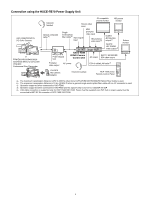
SD SDI video output HXC-FB80 HD Color Camera HXCU-FB80 4K/HD Camera Control supported only for RCP-1500/1501/1530. Power must be supplied via a PoE hub or power supply must be connected to EXT DC IN connector of RCP-1500/1501/1530. d) For details about a D-Sub remote adapter, contact a Sony service - Sony HXCU-FB80 | Operating Instructions - Page 5
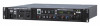
video output HXCU-FB80 4K/HD Sony CCFN-25/50/100/150/200/250 Hybrid Fiber Cable is used. b) HD TRUNK output supported when the signal format is set to 1080/50i HDR, 59.94i HDR. c) LAN cable connection is supported supported when connected to HXC-FB80. c) Operation supported when connected to HXC-FB80 - Sony HXCU-FB80 | Operating Instructions - Page 6
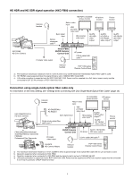
when Sony CCFN-25/50/100/150/200/250 Hybrid Fiber Cable is used. b) The maximum transmission distance is 10 km (32,800 ft) when a general single-mode optical fiber cable with an LC connector is used. c) Operation supported when connected to HXC-FB80. d) Operation supported when connected to HXC-FB80 - Sony HXCU-FB80 | Operating Instructions - Page 7
is being received (such as when the picture from the camera connected to the CCU is being used). When the CALL button on the camera or the RCP-1000 fiber cable. It flashes when there is a problem with the transmission between the camera and the CCU. c INTERCOM audio input/output and control block - Sony HXCU-FB80 | Operating Instructions - Page 8
ACTIVE button Activates the control panel to control the camera connected to the CCU (panel active state). When the button is lit, the IRIS/MB ACTIVE Panel or other device) is connected. Flashing: Indicates a connection problem with the external control equipment (RCP-1000-series Remote Control Panel - Sony HXCU-FB80 | Operating Instructions - Page 9
(iris adjustment) knob • MASTER BLACK (master black adjustment) knob Adjusts the master black manually. The adjustment can be set to relative or absolute value mode on the page in the CCU CONFIGURATION menu. The default value is relative value mode. For details, see "M BLACK" (page - Sony HXCU-FB80 | Operating Instructions - Page 10
a "Memory Stick" slot For service use only. b LAN jack instructions for this port. c HD PROMPTER (HD teleprompter connectors) (BNC type) When a camera that supports holder (optional) can be used to secure the power cord to the CCU. i REFERENCE (reference input) connectors (BNC type) IN: Inputs an - Sony HXCU-FB80 | Operating Instructions - Page 11
the signal interference. q TRUNK connector (D-sub 9-pin, RS-232C/RS-422A standard) Connects to an external device to provide a communication path via the CCU between that device and another external device connected to the TRUNK connector on the camera. You can switch between RS-232C and RS-422A - Sony HXCU-FB80 | Operating Instructions - Page 12
DIODE is set to OFF when this unit starts up. If you want to retain the LASER DIODE setting you have previously set, from the CCU CONFIGURATION menu, select C14 page, LASER DIODE ON BACKUP, then set to ENABLE. • Use general, single-mode optical fiber cables with an LC connector - Sony HXCU-FB80 | Operating Instructions - Page 13
Mode Setting" (page 14). When HD HDR mode is OFF 1 Display the CCU MENU page. 2 Display the OUTPUT FORMAT page of the SYSTEM OPERATION menu. < under SLOT-NO. SLOT1 connector Values in bold are valid when connected with HXC-FB80 only. CAMERA 1-1&2 (SDI-1, 2) FORMAT setting setting 1080/59.94P ( - Sony HXCU-FB80 | Operating Instructions - Page 14
(SDI-3, 4) setting M720/50P M625/50I SLOT2 connector Valid when connected with HXC-FB80 only. CAMERA FORMAT setting 1080/59.94P (OETF: SDR) 1080/29.97PsF When HD HDR mode is LIVE HDR Valid when connected with HXC-FB80 only. 1 Display the CCU MENU page. 2 Display the OUTPUT FORMAT page of the - Sony HXCU-FB80 | Operating Instructions - Page 15
4 Change the (S07) setting in the SYSTEM OPERATION menu to LIVE HDR. S07 TOP HDR MODE : cOFF SDR GAIN : ------ HDR BLACK OFFSET: ----- 5 Move the cursor to YES under MODE CHANGE OK?, and press the CONTROL button. S07 TOP MODE CHANGE OK? cYES NO HDR MODE :?OFF - Sony HXCU-FB80 | Operating Instructions - Page 16
extender) indicator Displayed when the lens extender is in use. Notes • Items that are turned off using the page settings of the CCU CONFIGURATION menu are not displayed. • A "-" mark is displayed for each item when a camera is not connected. h CC filter indicator Displays the current CC - Sony HXCU-FB80 | Operating Instructions - Page 17
(page 16) in the "Camera settings" section. System status *System Status 1/2* HXC-FB80 1080/59.94P (OETF : HLG_LIVE) Reference:Free Lock SLOT1-1&2:1080/59.94I SLOT1 setting of Return 3 Return-4: Return channel setting of Return 4 CCU hardware diagnostics *Diagnosis* 3/14 DPR :OK AT :OK Front - Sony HXCU-FB80 | Operating Instructions - Page 18
HALF Link Status :OK MacAddress: MAC address stored in CCU EEPROM Auto Negotiation: Auto negotiation setting Connection Speed: PLD Status: PLD status PLD AT: AT-PLD version AT POWER: AT board power supply status CCU DPR board diagnostics *DPR Diag* 11/14 Reference :HD 4K/HD CB :BAR 16:9(100 - Sony HXCU-FB80 | Operating Instructions - Page 19
camera hardware status. ROM version information *ROM Version* 14/14 CAMERA HXC-FB80 1.00 XX.XX.XX CCU HXCU-FB80 1.00 XX.XX.XX CAMERA: Camera model name and ROM version CCU: CCU model name and ROM version Setup Menu The CCU system and peripheral settings can be checked and modified using - Sony HXCU-FB80 | Operating Instructions - Page 20
and a list of selectable characters. Turning the CONTROL knob moves the cursor between characters. The following menu item has character strings: • CCU CONFIGURATION menu t page t BAR CHARACTER 1 Move the text cursor to the input position, then press the CONTROL knob. A second - Sony HXCU-FB80 | Operating Instructions - Page 21
COLOR SD ASPECT SD LB SEL H POSITION CENTER V POSITION CENTER H INTERP V INTERP RET-1 RET-2 RET-3 RET-4 HDR MODE SDR GAIN HDR BLACK OFFSET CCU CONFIGURATION menu COLOR BAR (C01) BAR CHARACTER (C02) MONITOR 1 (C03) MONITOR 2 (C04) MIC/AUDIO (C05) INTERCOM (C06) FRONT INCOM (C07) PROMPT/TRUNK (C08 - Sony HXCU-FB80 | Operating Instructions - Page 22
(N02) CNS SETTINGS (N03) NETWORK RESET (N04) IP ADDRESS SUBNET MASK DEFAULT GATEWAY SET AUTO NEGOTIATION CONNECTION SPEED DUPLEX MODE LINK CONDITION SET CNS MODE CCU NO MASTER IP ADDRESS ALL RESET 22 - Sony HXCU-FB80 | Operating Instructions - Page 23
name Page No. S01 S02 S03 Note FREQUENCY or CAMERA FORMAT mode setting changes take effect only after the CCU power supply is turned off and then on again. Item OUTPUT PIX LASER DIODE REFERENCE GENLOCK H STEP COARSE SC PHASE V PHASE SYNC OUT FREQUENCY - Sony HXCU-FB80 | Operating Instructions - Page 24
SYSTEM OPERATION Page name Page No. S04 Item SLOT NO 1-1&2 Settings Output format 1-3&4 Output format 2-1&2 Output format 2-3&4 Output format S05 3G-SDI Level A, Level B HD TRUNK OFF, ON COLOR SD ASPECT SD LB SEL H POSITION BT.709, BT.2020 SQUEEZE, EDGE CROP - Sony HXCU-FB80 | Operating Instructions - Page 25
Page name Page No. S06 Item RET-1 RET-2 RET-3 RET-4 S07 Valid when HDC-FB80 camera is connected Note HDR mode setting changes take effect only after the CCU power supply is turned off and then on again. HDR MODE SDR GAIN HDR BLACK OFFSET Settings Description SDI - Sony HXCU-FB80 | Operating Instructions - Page 26
CCU CONFIGURATION menu CCU CONFIGURATION Page name Page No. C01 Item 4K/HD BAR SEL Settings Description BAR 16:9 (100%), BAR 16:9 (75%), SMPTE 16:9 (BLACK), SMPTE - Sony HXCU-FB80 | Operating Instructions - Page 27
CCU CONFIGURATION Page name Page No. Item 2SI DIAMOND MARKER Settings OFF, ON Description Sets diamond mark superposition on the color bar for 4K 2 sample interleave - Sony HXCU-FB80 | Operating Instructions - Page 28
CCU CONFIGURATION Page name Page No. C04 C05 C06 Item LEVEL GATE Y LEVEL1 Y LEVEL2 GATE MARKER MODULATION MARKER CAM MIC GAIN CH1 - Sony HXCU-FB80 | Operating Instructions - Page 29
LEVEL CHROMA PIX LEVEL CHROMA NARROW, WIDE, -- -99 to 99 0 -99 to 99 0 -99 to 99 0 -99 to 99 0 Description CCU front panel MIC/PGM switch position (display only) CCU front panel INTERCOM switch position (display only) Headset microphone type connected to INTERCOM on the front panel CARBON: Carbon - Sony HXCU-FB80 | Operating Instructions - Page 30
previously displayed page function CONTROL knob operating mode settings STD: CONTROL knob clockwise rotation moves the CCU MENU pointer (,) down RVS: CONTROL knob counterclockwise rotation moves the CCU MENU pointer (,) down STD: CONTROL knob clockwise rotation displays the next page in the menu RVS - Sony HXCU-FB80 | Operating Instructions - Page 31
CCU CONFIGURATION Page name Page No. C15 Item Settings Description ASSIGNABLE/CUSTOM SW1 NOT ASSIGN, GAMMA OFF, DTL OFF, SD DTL OFF, BLK GAMMA, - Sony HXCU-FB80 | Operating Instructions - Page 32
CCU CONFIGURATION Page name Page No. C16 Item Settings VOLUME REL COEFF IRIS 1/1, 1/2, 1/4 M BLACK 1/1, 1/2, 1/4 R/B BLACK 1/1, 1/2, 1/4, (FLARE) R/B WHITE 1/1, 1/2, 1/4 CUSTOM 1/1, 1/2, 1/4 C17 SW BRIGHT (LOCK - Sony HXCU-FB80 | Operating Instructions - Page 33
), (UP) N03 SET CNS MODE LEGACY, BRIDGE, PC CONTROL, MCS CCU NO N04 MASTER IP ADDRESS ALL RESET 0 to 96, A to Z network master device, such as a master setup unit (for example, MSU-1000) CCU number settings 0 to 24 when CNS MODE is set to MCS Displays the PC IP - Sony HXCU-FB80 | Operating Instructions - Page 34
may be reduced correspondingly. About network security • SONY WILL NOT BE LIABLE FOR DAMAGES OF ANY KIND RESULTING FROM TRANSMISSION SPECIFICATIONS, OR SECURITY PROBLEMS OF ANY KIND. • Depending on Transmission Distance Unit and HD color camera The HXC-FB80/FB75/E75/P70 can be supplied with power - Sony HXCU-FB80 | Operating Instructions - Page 35
CCU: GEN LOCK NG CCU: DPR NG CCU: PS FAN NG CCU: PS CABLE OPEN CCU: PS RCP PWR SUPPLY NG CCU: AT NG CCU: RX WARNING CCU: CAM NEEDS VER.UP. CCU an HXC-FB80 running software version 1.00. When HDR MODE is set to LIVE HDR on the unit, this indicates a camera or camcorder that does not support HDR. - Sony HXCU-FB80 | Operating Instructions - Page 36
Fiber Cable CCFN-JC1 Joint Adaptor Service manual Related equipment HXC-FB80 HD Color Camera HXC-FB75/E75 HD Color Camera HXC-P70 HD Color Camera CA-FB70 HD notice. Note Always verify that the unit is operating properly before use. SONY WILL NOT BE LIABLE FOR DAMAGES OF ANY KIND INCLUDING, BUT NOT - Sony HXCU-FB80 | Operating Instructions - Page 37
No. Signal 24 G TALLY (X) IN 25 G TALLY (G) IN TRUNK connector Specifications ON: SHORT OFF: OPEN 5 1 9 6 No. Signal 1 NC 2 • RX IN (RS-232C) • RX1(-) IN (RS-422A) 3 • TX OUT (RS-232C) • TX1(-) OUT (RS-422A) 4 NC 5 GND 6 NC 7 TX1(+) OUT (RS-422A) 8 RX1(+) IN (RS-422A) - Sony HXCU-FB80 | Operating Instructions - Page 38
Sony Corporation
-
 1
1 -
 2
2 -
 3
3 -
 4
4 -
 5
5 -
 6
6 -
 7
7 -
8
-
9
-
10
-
11
-
12
-
13
-
14
-
15
-
16
-
17
-
18
-
19
-
20
-
21
-
22
-
23
-
24
-
25
-
26
-
27
-
28
-
29
-
30
-
31
-
32
-
33
-
34
-
35
-
36
-
37
-
38
 |
 |

4K/HD Camera Control
Unit
Operating Instructions
Before operating the unit, please read this manual thoroughly
and retain it for future reference.
HXCU-FB80
4-734-405-
12
(1)
© 2017 Sony Corporation