Sony KDL-52V4100 Service Manual
Sony KDL-52V4100 - 52" LCD TV Manual
 |
UPC - 027242736177
View all Sony KDL-52V4100 manuals
Add to My Manuals
Save this manual to your list of manuals |
Sony KDL-52V4100 manual content summary:
- Sony KDL-52V4100 | Service Manual - Page 1
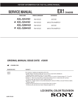
INFORMATION FOR THE FOLLOWING MANUAL: SERVICE MANUAL MODEL NAME REMOTE COMMANDER KDL-52V4100 ☛ KDL-52V4100 KDL-52W4100 ☛ KDL-52W4100 RM-YD023 RM-YD023 RM-YD023 RM-YD023 EX1 CHASSIS DESTINATION US/CND MX/LATIN AMERICA US/CND MX/LATIN AMERICA ORIGINAL MANUAL ISSUE DATE: 4/2008 ☛ :UPDATED ITEM - Sony KDL-52V4100 | Service Manual - Page 2
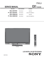
MANUAL MODEL NAME REMOTE COMMANDER KDL-52V4100 ☛ KDL-52V4100 KDL-52W4100 ☛ KDL-52W4100 RM-YD023 RM-YD023 RM-YD023 RM-YD023 Self Diagnosis Supported model EX1 CHASSIS DESTINATION US/CND MX/LATIN AMERICA US/CND MX/LATIN AMERICA 9-883-782-02 KDL-52W4100 RM-YD023 LCD DIGITAL COLOR TELEVISION - Sony KDL-52V4100 | Service Manual - Page 3
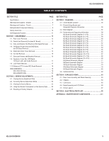
, H4 Board, and Light Guide Removal 17 1-9. LCD Panel Removal 17 1-10.Balancer (ETC-Inverter MT) Board Removal 18 WIRE DRESSING 19 KDL-52V4100 Only 19 KDL-52W4100 Only 35 SECTION 2: SERVICE ADJUSTMENTS 53 2-1. Viewing Service Adjustment Data 53 2-2. Accessing Service Adjustment Mode 53 - Sony KDL-52V4100 | Service Manual - Page 4
KDL-52V4100/52W4100 Blu-ray Disc is a trademark. "BRAVIA" and , S-Force, BRAVIA Sync, , DMex and "x.v. Color" are trademarks or registered marks of Sony in the TV Guide On Screen system and cannot guarantee service availability in your area. In no event shall Gemstar-TV Guide International, Inc - Sony KDL-52V4100 | Service Manual - Page 5
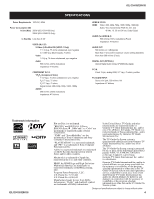
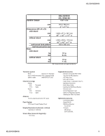
Display) Panel Display Resolution (horizontal x vertical) 1,920 dots x 1,080 lines Screen Size (measured diagonally) ~ 52 inches Supplied Accessories Remote Commander RM-YD023 Two Size AA (R6) Batteries AC Power Cord HD15-HD15 Cable Cable Holder (1 attached to the TV) Operating Instructions - Sony KDL-52V4100 | Service Manual - Page 6
whose part numbers appear as shown in this manual or in supplements published by Sony. Circuit adjustments that are critical for safe operation are identified in this manual. Follow these procedures whenever critical components are replaced or improper operation is suspected. KDL-52V4100/52W4100 6 - Sony KDL-52V4100 | Service Manual - Page 7
KDL-52V4100/52W4100 WARNINGS AND CAUTIONS - FRENCH ATTENTION!! Ces instructions de service sont à l'usage du personnel de service qualifié seulement. Pour prévenir le risque les remplacer que par des composants Sony dont le numero de piece est indique dans le present manuel ou dans des supplements - Sony KDL-52V4100 | Service Manual - Page 8
KDL-52V4100/52W4100 SAFETY-RELATED COMPONENT WARNING There are critical components used in LCD color TVs that are important for safety. These components are identified with shading and ! mark on the schematic diagrams and the electrical parts list. It is essential that these critical parts be - Sony KDL-52V4100 | Service Manual - Page 9
servicing of these boards requires special precautions to be taken as outlined below. KDL-52V4100/52W4100 It is strongly recommended to use Lead Free Solder material in order to guarantee optimal quality of new solder joints. Lead Free Solder is available under the following part numbers : Part - Sony KDL-52V4100 | Service Manual - Page 10
if the screw is at ground potential (see Figure B). To Exposed Metal Parts on Set 0.15 μF AC Voltmeter (0.75V) Earth Ground Trouble Light AC Outlet Box Ohmmeter Cold-water Pipe Figure A. Using an AC voltmeter to check AC leakage. Figure B. Checking for earth ground. KDL-52V4100/52W4100 10 - Sony KDL-52V4100 | Service Manual - Page 11
blinks continuously, this may indicate that the TV needs servicing. PIC OFF/ TIMER LED Green or Orange LED * Lights up in green when Picture Off is activated * Lights up in orange when the timer is set When timer is set, the LED remains lit even when the TV is turned off. KDL-52V4100/52W4100 11 - Sony KDL-52V4100 | Service Manual - Page 12
KDL-52V4100/52W4100 2 times 5 times LED ON 0.3 sec. LED OFF 0.3 sec. LED OFF 3 sec. Viewing the Self Check Diagnostic List 1. TV must be in standby mode. (Power off). 2. Press the following buttons on the Remote Commander within a second of each other: DISPLAY Channel 5 The Self Check list - Sony KDL-52V4100 | Service Manual - Page 13
SECTION 1: DISASSEMBLY 1-1. REAR COVER REMOVAL 1 Remove 2 screws from Terminal Position 2 Remove 6 screws 3 Remove 21 screws Rear Cover KDL-52V4100/52W4100 1 2 3 1-2. SWITCH UNIT REMOVAL (CONTAINS H1 BOARD) 1 Remove Switch Unit from bezel (Contains H1 Board) 2 Disconnect 1 connector Switch Unit - Sony KDL-52V4100 | Service Manual - Page 14
Board Side Jack Bracket KDL-52V4100/52W4100 BU Shield 2 4 3 1-4. G5 BOARD (POWER UNIT) AND D4Z BOARD, AND D5 BOARD REMOVAL 1 Disconnect 3 connectors 2 Remove 4 screws 3 Disconnect 6 connectors (KDL-52V4100 ONLY) Disconnect 7 connectors (KDL-52W4100 ONLY) 4 Remove 6 screws 5 Release 5 Board - Sony KDL-52V4100 | Service Manual - Page 15
1-5. STAND AND UNDER COVER REMOVAL 1 Remove 4 screws 2 Remove 1 screw 1 Under Cover KDL-52V4100/52W4100 Stand Assembly 2 1-6. AC INLET REMOVAL 1 Remove 2 screws 2 Remove 1 screw 2 AC Bracket AC Inlet 1 Bottom Bracket KDL-52V4100/52W4100 15 - Sony KDL-52V4100 | Service Manual - Page 16
2 screws from Spine Frames and Bottom Bracket 9 Remove 8 screws from Spine Frames 10 Remove 2 screws from Spine Frames and Bezel 11 Remove 4 screws from both Bottom Vesa Brackets 12 Remove 4 screws from Bottom Bracket KDL-52V4100/52W4100 3 2 D5 Support Frame 1 4 Main Bracket Top Vesa Bracket - Sony KDL-52V4100 | Service Manual - Page 17
which side is attached to the TCON and which side is attached to the BU Board. Refer to Wire Dressing Illustration on Page 32 for KDL-52V4100 models or Page 50 for KDL-52W4100 models. 1 Disconnect 3 connectors 2 Remove 2 screws 1 2 LCD Panel Bezel KDL-52V4100/52W4100 17 - Sony KDL-52V4100 | Service Manual - Page 18
KDL-52V4100/52W4100 LCD Panel 2 1 1 Balancer Board Shield WARNING! NEVER REMOVE THE SCREWS SECURING THE PLASTIC STRIP HOLDING THE LAMP SOCKETS DAMAGE TO THE . BACKLIGHT TUBES WILL OCCUR! REMOVE SCREWS SECURING SHIELD REMOVE CONNECTORS AND PULL BOARDS TO THE RIGHT SHIELD REMOVAL KDL-52V4100 - Sony KDL-52V4100 | Service Manual - Page 19
WIRE DRESSING Apply Sheet Core C over RED UL tape once harness is centered over panel. KDL-52V4100/52W4100 LEGEND SHEET CORE C (2-688-011-01) QTY=11 LCD TAPE (2-688-062-01) QTY=6 SLIDE CLAMP (2-650-770-01) QTY=1 (UPPER VESA SUPPORT) SLIDE CLAMP (2-650-770-11) QTY=12 CHO-FAB TAPE (2-888-494-01) QTY - Sony KDL-52V4100 | Service Manual - Page 20
ONLY H Boards/Speaker Harness Apply Sheet Core C over UL tape as shown. KDL-52V4100/52W4100 LEGEND SHEET CORE C (2-688-011-01) QTY=11 LCD TAPE (2-688-062-01) QTY=6 SLIDE CLAMP (2-650-770-01) QTY=1 (UPPER VESA SUPPORT) SLIDE CLAMP (2-650-770-11) QTY=12 CHO-FAB TAPE (2-888-494-01) QTY=1 HIMELON - Sony KDL-52V4100 | Service Manual - Page 21
Apply Sheet Core C over BLACK UL TAPE on Harness Assy. Apply LCD TAPE over panel sharp edge. 4 KDL-52V4100/52W4100 LEGEND SHEET CORE C (2-688-011-01) QTY=11 LCD TAPE (2-688-062-01) QTY=6 SLIDE CLAMP (2-650-770-01) QTY=1 (UPPER VESA SUPPORT) SLIDE CLAMP (2-650-770-11) QTY=12 CHO-FAB TAPE (2-888 - Sony KDL-52V4100 | Service Manual - Page 22
Harness NOTE routing of H3E Board wires. BE CAREFUL of Pinch Points (circled in RED) KDL-52V4100/52W4100 LEGEND SHEET CORE C (2-688-011-01) QTY=11 LCD TAPE (2-688-062-01) QTY=6 SLIDE CLAMP (2-650-770-01) QTY=1 (UPPER VESA SUPPORT) SLIDE CLAMP (2-650-770-11) QTY=12 CHO-FAB TAPE (2-888-494-01) QTY - Sony KDL-52V4100 | Service Manual - Page 23
tape as shown. Use BLACK UL TAPE on the connector assy as guide where To place himelon tape. KDL-52V4100/52W4100 LEGEND SHEET CORE C (2-688-011-01) QTY=11 LCD TAPE (2-688-062-01) QTY=6 SLIDE CLAMP (2-650-770-01) QTY=1 (UPPER VESA SUPPORT) SLIDE CLAMP (2-650-770-11) QTY=12 CHO-FAB TAPE (2-888-494 - Sony KDL-52V4100 | Service Manual - Page 24
KDL-52V4100 ONLY Panel Balancer Board Conn Assy. Detail Use Plastic Pin as guide for Black UL Tape position. Wires CANNOT be below level of this Plastic pin (pinch point). Apply Sheet Core C to secure wires. KDL-52V4100/52W4100 LEGEND SHEET CORE C (2-688-011-01) QTY=11 LCD TAPE (2-688-062-01) QTY - Sony KDL-52V4100 | Service Manual - Page 25
Tape on Speaker 3 Dress Speaker wires and Main Harness In Sheet Core C KDL-52V4100/52W4100 LEGEND SHEET CORE C (2-688-011-01) QTY=11 LCD TAPE (2-688-062-01) QTY=6 SLIDE CLAMP (2-650-770-01) QTY=1 (UPPER VESA SUPPORT) SLIDE CLAMP (2-650-770-11) QTY=12 CHO-FAB TAPE (2-888-494-01) QTY=1 HIMELON TAPE - Sony KDL-52V4100 | Service Manual - Page 26
ONLY BU Board 11 Bracket 10 9 1 2 KDL-52V4100/52W4100 LEGEND SHEET CORE C (2-688-011-01) QTY=11 LCD TAPE (2-688-062-01) QTY=6 SLIDE CLAMP (2-650-770-01) QTY=1 (UPPER VESA SUPPORT) SLIDE CLAMP (2-650-770-11) QTY=12 CHO-FAB TAPE (2-888-494-01) QTY=1 HIMELON TAPE (2-661-260-01) QTY=1 3 4 5 Side - Sony KDL-52V4100 | Service Manual - Page 27
ONLY BU Board Bracket- II 3 4 5 9 8 KDL-52V4100/52W4100 KDL-52V4100/52W4100 LEGEND SHEET CORE C (2-688-011-01) QTY=11 LCD TAPE (2-688-062-01) QTY=6 SLIDE CLAMP (2-650-770-01) QTY=1 (UPPER VESA SUPPORT) SLIDE CLAMP (2-650-770-11) QTY=12 CHO-FAB TAPE (2-888-494-01) QTY=1 HIMELON TAPE (2-661 - Sony KDL-52V4100 | Service Manual - Page 28
ONLY Balancer Board Wire Dressing 10 PANEL 6 Balancer-L NEW Hirose MDF-61 Connector on both balancer boards. D4Z Board KDL-52V4100/52W4100 LEGEND SHEET CORE C (2-688-011-01) QTY=11 LCD TAPE (2-688-062-01) QTY=6 SLIDE CLAMP (2-650-770-01) QTY=1 (UPPER VESA SUPPORT) SLIDE CLAMP (2-650-770-11) QTY - Sony KDL-52V4100 | Service Manual - Page 29
ONLY INSTALLATION PROCEDURE FOR MDF-61 CONNECTOR KDL-52V4100/52W4100 LEGEND SHEET CORE C (2-688-011-01) QTY=11 LCD TAPE (2-688-062-01) QTY=6 SLIDE CLAMP (2-650-770-01) QTY=1 (UPPER VESA SUPPORT) SLIDE CLAMP (2-650-770-11) QTY=12 CHO-FAB TAPE (2-888-494-01) QTY=1 HIMELON TAPE (2-661-260-01) QTY - Sony KDL-52V4100 | Service Manual - Page 30
ONLY D4Z/D5 & G5 Board Wire Routing 7 8 11 10 1 9 2 KDL-52V4100/52W4100 LEGEND SHEET CORE C (2-688-011-01) QTY=11 LCD TAPE (2-688-062-01) QTY=6 SLIDE CLAMP (2-650-770-01) QTY=1 (UPPER VESA SUPPORT) SLIDE CLAMP (2-650-770-11) QTY=12 CHO-FAB TAPE (2-888-494-01) QTY=1 HIMELON TAPE (2-661-260 - Sony KDL-52V4100 | Service Manual - Page 31
Places) as shown. Apply Slide Clamp (4 Places) as shown. 2 3 5 KDL-52V4100/52W4100 LEGEND SHEET CORE C (2-688-011-01) QTY=11 LCD TAPE (2-688-062-01) QTY=6 SLIDE CLAMP (2-650-770-01) QTY=1 (UPPER VESA SUPPORT) SLIDE CLAMP (2-650-770-11) QTY=12 CHO-FAB TAPE (2-888-494-01) QTY=1 HIMELON TAPE (2-661 - Sony KDL-52V4100 | Service Manual - Page 32
LVDS Cable to panel and BU Board bracket. MAKE SURE clip is CENTERED Between Guides on Main Bracket BEFORE installing 11 Screw. CAUTION: Securing grounding clip with 3x5mm Screw is CRITICAL FOR EMI 1 3 KDL-52V4100/52W4100 LEGEND SHEET CORE C (2-688-011-01) QTY=11 LCD TAPE (2-688-062 - Sony KDL-52V4100 | Service Manual - Page 33
KDL-52V4100/52W4100 KDL-52V4100 ONLY LVDS Cable Routing/Dress (CRITICAL FOR EMI) Apply Cho-Fab Tape P/N:2-888-494-01 Over opening in LVDS Cable near TCON This Cho-Fab tape (conductive) is CRITICAL for EMI. The tape MUST contact panel/LVDS. LEGEND SHEET CORE C (2-688-011-01) QTY=11 LCD TAPE (2-688- - Sony KDL-52V4100 | Service Manual - Page 34
Inlet Wire. 12 KDL-52V4100/52W4100 Dress AC Cables to the SIDE Of the G5 Board. Reason: If cables are not pushed to the side they will touch rear cover - N.G. LEGEND SHEET CORE C (2-688-011-01) QTY=11 LCD TAPE (2-688-062-01) QTY=6 SLIDE CLAMP (2-650-770-01) QTY=1 (UPPER VESA SUPPORT) SLIDE CLAMP - Sony KDL-52V4100 | Service Manual - Page 35
CORE C (2-688-011-01) QTY=12 LCD TAPE (2-688-062-01) QTY=4 SLIDE CLAMP (2-650-770-01) QTY=1 (UPPER VESA SUPPORT) SLIDE CLAMP (2-650-770-11) QTY=11 Center RED UL tape on the harness to the Center of the panel. Use Plastic Boss and "dimple" as guides where center of panel is. KDL-52V4100/52W4100 35 - Sony KDL-52V4100 | Service Manual - Page 36
KDL-52W4100 ONLY H Boards/Speaker Harness Apply Sheet Core C over UL tape as shown. KDL-52V4100/52W4100 LEGEND SHEET CORE C (2-688-011-01) QTY=12 LCD TAPE (2-688-062-01) QTY=4 SLIDE CLAMP (2-650-770-01) QTY=1 (UPPER VESA SUPPORT) SLIDE CLAMP (2-650-770-11) QTY=11 1 3 2 KDL-52V4100/52W4100 36 - Sony KDL-52V4100 | Service Manual - Page 37
-52W4100 ONLY H Boards/Speaker Harness: Lighted SONY Logo Apply LCD Tape to sharp edge of panel. 1 KDL-52V4100/52W4100 LEGEND SHEET CORE C (2-688-011-01) QTY=12 LCD TAPE (2-688-062-01) QTY=4 SLIDE CLAMP (2-650-770-01) QTY=1 (UPPER VESA SUPPORT) SLIDE CLAMP (2-650-770-11) QTY=11 KDL-52V4100/52W4100 - Sony KDL-52V4100 | Service Manual - Page 38
Combination H Board/Speaker Harness Apply Sheet Core C over BLACK UL TAPE on Harness Assy. 4 KDL-52V4100/52W4100 LEGEND SHEET CORE C (2-688-011-01) QTY=12 LCD TAPE (2-688-062-01) QTY=4 SLIDE CLAMP (2-650-770-01) QTY=1 (UPPER VESA SUPPORT) SLIDE CLAMP (2-650-770-11) QTY=11 KDL-52V4100/52W4100 38 - Sony KDL-52V4100 | Service Manual - Page 39
NOTE routing of H3E Board wires. BE CAREFUL of Pinch Points (circled in RED) Apply LCD Tape to sharp edge of panel. 2 KDL-52V4100/52W4100 LEGEND SHEET CORE C (2-688-011-01) QTY=12 LCD TAPE (2-688-062-01) QTY=4 SLIDE CLAMP (2-650-770-01) QTY=1 (UPPER VESA SUPPORT) SLIDE CLAMP (2-650-770-11) QTY=11 - Sony KDL-52V4100 | Service Manual - Page 40
H Board/Speaker Harness 5 Apply Sheet Core C to Main Harness and panel in location shown. KDL-52V4100/52W4100 KDL-52V4100/52W4100 LEGEND SHEET CORE C (2-688-011-01) QTY=12 LCD TAPE (2-688-062-01) QTY=4 SLIDE CLAMP (2-650-770-01) QTY=1 (UPPER VESA SUPPORT) SLIDE CLAMP (2-650-770-11) QTY=11 40 - Sony KDL-52V4100 | Service Manual - Page 41
as guide where To place himelon tape. KDL-52V4100/52W4100 LEGEND SHEET CORE C (2-688-011-01) QTY=12 LCD TAPE (2-688-062-01) QTY=4 SLIDE CLAMP (2-650-770-01) QTY=1 (UPPER VESA SUPPORT) SLIDE CLAMP (2-650-770-11) QTY=11 8 6 7 NOTE DETAIL PHOTO of Conn Assy. Wire are ABOVE plastic CLIP on panel - Sony KDL-52V4100 | Service Manual - Page 42
KDL-52W4100 ONLY Panel Balancer Board Conn Assy. Detail Use Plastic Pin as guide for Black UL Tape position. Wires CANNOT be below level of this Plastic pin (pinch point). Apply Sheet Core C to secure wires. KDL-52V4100/52W4100 LEGEND SHEET CORE C (2-688-011-01) QTY=12 LCD TAPE (2-688-062-01) QTY - Sony KDL-52V4100 | Service Manual - Page 43
Tape to Left Speaker wires. NO NEED to put LCD Tape on Speaker 3 Dress Speaker wires and Main Harness In Slide Clamp KDL-52V4100/52W4100 LEGEND SHEET CORE C (2-688-011-01) QTY=12 LCD TAPE (2-688-062-01) QTY=4 SLIDE CLAMP (2-650-770-01) QTY=1 (UPPER VESA SUPPORT) SLIDE CLAMP (2-650-770-11) QTY=11 - Sony KDL-52V4100 | Service Manual - Page 44
KDL-52W4100 ONLY BU-Board Bracket- II 1 2 3 5 4 KDL-52V4100/52W4100 KDL-52V4100/52W4100 LEGEND SHEET CORE C (2-688-011-01) QTY=12 LCD TAPE (2-688-062-01) QTY=4 SLIDE CLAMP (2-650-770-01) QTY=1 (UPPER VESA SUPPORT) SLIDE CLAMP (2-650-770-11) QTY=11 44 - Sony KDL-52V4100 | Service Manual - Page 45
KDL-52W4100 ONLY Balancer Board Wire Dressing 9 6 NEW Hirose MDF-61 Connector on both balancer boards. KDL-52V4100/52W4100 LEGEND SHEET CORE C (2-688-011-01) QTY=12 LCD TAPE (2-688-062-01) QTY=4 SLIDE CLAMP (2-650-770-01) QTY=1 (UPPER VESA SUPPORT) SLIDE CLAMP (2-650-770-11) QTY=11 KDL-52V4100/ - Sony KDL-52V4100 | Service Manual - Page 46
ONLY INSTALLATION PROCEDURE FOR MDF-61 CONNECTOR KDL-52V4100/52W4100 LEGEND SHEET CORE C (2-688-011-01) QTY=12 LCD TAPE (2-688-062-01) QTY=4 SLIDE CLAMP (2-650-770-01) QTY=1 (UPPER VESA SUPPORT) SLIDE CLAMP (2-650-770-11) QTY=11 STEP1: ALIGN CONNECTOR STEP2: INSTALL CONNECTOR STEP3: PUSH DOWN - Sony KDL-52V4100 | Service Manual - Page 47
& G5 Board Wire Routing 7 KDL-52V4100/52W4100 LEGEND SHEET CORE C (2-688-011-01) QTY=12 LCD TAPE (2-688-062-01) QTY=4 8 1 9 SLIDE CLAMP (2-650-770-01) QTY=1 (UPPER VESA SUPPORT) SLIDE CLAMP (2-650-770-11) QTY=11 NOTE: Slide Clamp on end of Upper VESA Support is -01 (larger size). Color - Sony KDL-52V4100 | Service Manual - Page 48
/D5 & G5 Board Wire Routing ARROW COLOR CODE G5 to D5 (3P-YELLOW UL) D4Z to G5 (8P) D4Z to D5 (10P) 9 1 2 KDL-52V4100/52W4100 LEGEND SHEET CORE C (2-688-011-01) QTY=12 LCD TAPE (2-688-062-01) QTY=4 SLIDE CLAMP (2-650-770-01) QTY=1 (UPPER VESA SUPPORT) SLIDE CLAMP (2-650-770-11) QTY=11 - Sony KDL-52V4100 | Service Manual - Page 49
Apply Tape, LCD as shown. 9 Apply Slide Clamp (4 Places) as shown. 1 KDL-52V4100/52W4100 LEGEND SHEET CORE C (2-688-011-01) QTY=12 LCD TAPE (2-688-062-01) QTY=4 SLIDE CLAMP (2-650-770-01) QTY=1 (UPPER VESA SUPPORT) SLIDE CLAMP (2-650-770-11) QTY=11 4 2 1 9 8 3 4 KDL-52V4100/52W4100 49 - Sony KDL-52V4100 | Service Manual - Page 50
SUPPORT) SLIDE CLAMP (2-650-770-11) QTY=11 10 1 9 1 Apply 3x8mm Screw 2 to secure LVDS Cable to panel and BU Board bracket. MAKE SURE that the LVDS clip is Centered between guides on Main Bracket and Panel BEFORE applying screw. LVDS CLIP/SCREW IS CRITICAL FOR EMI KDL-52V4100/52W4100 - Sony KDL-52V4100 | Service Manual - Page 51
Inlet Wire. 11 KDL-52V4100/52W4100 Dress AC Cables to the SIDE Of the G5-Bd. Reason: If cables are not pushed to the side they will touch rear cover - N.G. LEGEND SHEET CORE C (2-688-011-01) QTY=12 LCD TAPE (2-688-062-01) QTY=4 SLIDE CLAMP (2-650-770-01) QTY=1 (UPPER VESA SUPPORT) SLIDE CLAMP - Sony KDL-52V4100 | Service Manual - Page 52
be firmly taped to panel. (EMI CRITICAL) Route wires in Slide Clamp as shown. 12 KDL-52V4100/52W4100 LEGEND SHEET CORE C (2-688-011-01) QTY=12 LCD TAPE (2-688-062-01) QTY=4 SLIDE CLAMP (2-650-770-01) QTY=1 (UPPER VESA SUPPORT) SLIDE CLAMP (2-650-770-11) QTY=11 9 8 1 KDL-52V4100/52W4100 52 - Sony KDL-52V4100 | Service Manual - Page 53
ADJ 001 R_DRV SERVICE 00100 DIGITAL PROGRAM : H801.03 0070 DATA : S001000 BE PROGRAM : TM1.000 NVM : TD1.000 PACK : TP1.000 BOOT : TB1.000 VOLUME+ QM INFO Press JUMP 0 0 SERVICE DTV JUMP Sample Service Menus RM-YD023 The first service menu (TV) displays. KDL-52V4100/52W4100 53 - Sony KDL-52V4100 | Service Manual - Page 54
the User Controls and Channel Memory settings to the preset factory conditions. 1. While holding down the on the Remote Commander, press the POWER button on the Front Panel of the set. The set restarts and displays the initial setup screen. This may take several minutes. KDL-52V4100/52W4100 54 - Sony KDL-52V4100 | Service Manual - Page 55
, comme maque. NOTE: The components identified by a red outline and a mark contain confidential information. Specific instructions must be adhered to whenever these components are repaired and/or replaced. See Appendix A: Encryption Key Components in the back of this manual. KDL-52V4100/52W4100 55 - Sony KDL-52V4100 | Service Manual - Page 56
: MPS METALIZED POLYESTER : MPP METALIZED POLYPROPYLENE : ALB BIPOLAR : ALT HIGH TEMPERATURE : ALR HIGH RIPPLE KDL-52V4100/52W4100 Terminal name of semiconductors in silk screen * printed circuit ( ) Device Printed symbol 1 Transistor Terminal name Collector Base Emitter Circuit 2 Transistor - Sony KDL-52V4100 | Service Manual - Page 57
/52W4100 KDL-52V4100/52W4100 for ATSC Video SW CVBS for PAP CXA2241 for Slicer ( 90h ) HDMI EQ_SW AD8197 4 to 1 ( 9Eh ) IIC DDC Audio Compound IC YOUT for Slicer x245 Digital Video ITU-R BT.656 ITU-R BT.1120 CPU Demod. MPEG2 Dec. 3D GPX CC/PL Sub Chroma EPG(Gemstar) USB Ether Digital - Sony KDL-52V4100 | Service Manual - Page 58
3-4. SCHEMATICS AND SUPPORTING INFORMATION BU BOARD SCHEMATIC DIAGRAM (1 OF 12) 1 | 2 | 3 | 4 | 5 | 6 | 7 | 8 | 9 | BL2 - R3 N L2 - R4 *J1101 O - P KDL-52V4100/52W4100 VD1001 GND 4 4 2 2 6 3 3 1 1 VD1003 RT3S02M-T111-1 Q1304 2VppOUT sub-Display Graphics R1314 1k 1/16W RN - Sony KDL-52V4100 | Service Manual - Page 59
35 CS 36 GPIO1 37 GPIO2 38 /MUTE 39 /RESET 40 DVSS4 41 VR_DIG3 42 DVDD4 43 LINEIN1L 44 LINEIN1R LINEIN9R AVSS_LI3 LINEIN10L LINEIN10R BIAS_REF BG_REF V1P5_REF AVDD_REF AVDD_LO 51 52 53 54 55 56 57 58 59 60 61 62 14 12 10 8 6 4 2 10k RB2014 KDL-52V4100/52W4100 KDL-52V4100/52W4100 59 - Sony KDL-52V4100 | Service Manual - Page 60
P52 57 A17/P51 56 A16/P50 55 VDDI 54 VSS 53 VDDE 52 A15 51 A14 50 A13 49 A12 48 A11 47 A10 46 A9 9 A19 10 NC DQ5 40 AD4 DQ12 39 11 WE# DQ4 38 12 RESET# VCC 37 13 NC AD3 DQ11 36 14 NC DQ3 35 AD2 15 RY/ ICS2 11 ICS1 12 ICS0 13 GND 14 ICLK CN3001 14P KDL-52V4100/52W4100 KDL-52V4100/52W4100 60 - Sony KDL-52V4100 | Service Manual - Page 61
C4715 0.1 16V 1005 GND RB4704 100 RB4710 100 2468 1357 D4701 RB521S-30-TE61 Reset:Low RESET_TR REG5V C4716 0.001 50V X7R 1005 C4717 0.1 16V MPU_DLAT 1005 1k RB4708 POWER 48 POWER 49 POWER 50 POWER 51 POWER GND BLK CN4700 51P TO PANEL A-1506-055-A BU-P4 KDL-52V4100/52W4100 61 - Sony KDL-52V4100 | Service Manual - Page 62
C4926 0.1 16V 1005 GND C4915 10 6.3V X6S 2012 C4921 10 6.3V X6S 2012 GND BU 5/12 TRIDENT DDR SDRAM P A-1506-055-A BU-P5 KDL-52V4100/52W4100 KDL-52V4100/52W4100 62 - Sony KDL-52V4100 | Service Manual - Page 63
58 VTTI 57 IP_D1 56 IN_D1 55 AVCC 54 IP_D0 53 IN_D0 52 AVEE 51 C5321 0.01 25V X7R 1005 RX2_2R+ RX2_2R- RX1_2R+ ON0 OP0 VTTO ON1 OP1 DVCC ON2 OP2 VTTO ON3 OP3 RESET PP_PRE0 PP_PRE1 DVCC PP_OCL I2C_SCL I2C_SDA 26 27 28 29 30 A-1506-055-A BU-P6 KDL-52V4100/52W4100 KDL-52V4100/52W4100 63 - Sony KDL-52V4100 | Service Manual - Page 64
C7161 10 6.3V X6S 2012 C7163 10 6.3V X6S 2012 C7165 10 6.3V X6S 2012 C7168 0.1 16V X7R 1005 C7184 220 16V GND BU 7/12 POWER SUPPLY A-1506-055-A BU-P7 21 | KDL-52V4100/52W4100 KDL-52V4100/52W4100 64 - Sony KDL-52V4100 | Service Manual - Page 65
CL7206 42 31 42 31 8642 7531 UART1_RXD UART1_TXD TO TV GPX_HSYNC_IN GPX_VSYNC_IN UART0_RXD UART0_TXD TO DIAG GPX_PCLK_IN RB7208 10k RB7210 ET7205 ET7206 ET7207 GND BU 8/12 X245 GND/PWR/XTAL/ PLL/RESET/PERIPHERAL P A-1506-055-A BU-P8 KDL-52V4100/52W4100 KDL-52V4100/52W4100 65 - Sony KDL-52V4100 | Service Manual - Page 66
IC7000 215-0684001-00 AUDIO_MCLK FAD5_PAD D3.3V R7443 10k 1/16W CHIP BU 9/12 X245 DDR2/FLASH/NVM/FLEXBUS/STRAP A-1506-055-A BU-P9 KDL-52V4100/52W4100 KDL-52V4100/52W4100 66 - Sony KDL-52V4100 | Service Manual - Page 67
(6) MPEG_D(7) MPEG_SYNC MPEG_DATA_EN MPEG_ERR AF30 AK28 AK29 AJ28 AJ29 AJ30 AH28 AH29 AH30 AG29 AG28 AG30 IC7000 215-0684001-00 O - P A-1506-055-A BU-P10 KDL-52V4100/52W4100 KDL-52V4100/52W4100 67 - Sony KDL-52V4100 | Service Manual - Page 68
A5V_VIF AFT_OUT DET_OUT AGND ST_ID SAP_ID MODO F_MONO A9V_MPX R_OUT L_OUT A5V_DD GND GND SONY TUNER BTF-CA422T D3.3V CL7615 R7609 3.3k 1/16W CHIP C7649 4.7 10V GND TV_M_MON_V BU 11/12 X245 FRONTEND/ADC/GPIOC/TUNER P KDL-52V4100/52W4100 A-1506-055-A BU-P11 KDL-52V4100/52W4100 68 - Sony KDL-52V4100 | Service Manual - Page 69
MAIN_DIN DIGITAL VIDEO ITU-R BT601 OUT (YC:88) X245 HDMI1.2 (2PORTS) X245 WXGA PANEL OUTPUT LVDS G3 TXOUT_L0N G4 TXOUT_L0P F1 TXOUT_L1N F2 TXOUT_L1P E3 TXOUT_L2N E4 TXOUT_L2P D1 12/12 X245 DVO OUTPUT (ITU656.GRAPHICS) P KDL-52V4100/52W4100 A-1506-055-A BU-P12 KDL-52V4100/52W4100 69 - Sony KDL-52V4100 | Service Manual - Page 70
KDL-52V4100/52W4100 BU [VIDEO SW & I, O, AUDIO, BE MICRO, TRIDENT WX-2, TRIDENT DDR SDRAM, HDMI, PC, POWER SUPPLY, X245 GND, PWR, XTAL, PLL, RESET, PERIPHERAL, X245 DDR2, FLASH, NVM, FLEXBUS, STRAP, X245 AUDIO IF, USB1.1, X245 FRONTEND, ADC, GPIOC, TUNER, X245 DVO OUTPUT (ITU656.GRAPHICS)] - Sony KDL-52V4100 | Service Manual - Page 71
-CP *R6762 150 1/10W RN-CP *R6764 150 1/10W RN-CP *R6768 180 1/10W RN-CP 0.5% 1608 *R6716 3.9k 1/10W RN-CP 5% - P KDL-52V4100/52W4100 JW6712 7.5 JW6713 7.5 JW6710 7.5 JW6711 7.5 D6704 MC2837 EY6722 EY6723 *C6709 27p 6.3kV SL JL6727 1 GND_2 *C6710 3300p 50V SL 1608 EY6724 D6705 MC2837 - Sony KDL-52V4100 | Service Manual - Page 72
D4Z [POWER] COMPONENT SIDE A - B - C - D - E - F - G - H - I - J - K - L - M - KDL-52V4100/52W4100 1 | VCC(12V) FB FB GND GND LD LD 2 | 3 | JW6606 JW6605 4 | 5 | NC NC CN6708 ET6702 CN6701 7 1 JW6724 9 CN6706 1 To Balancer 40 JW6714 46 JW6715 52 JW6716 JW6726 JW6725 - Sony KDL-52V4100 | Service Manual - Page 73
KDL-52V4100/52W4100 ☛D5 BOARD SCHEMATIC DIAGRAM 1 | 2 | 3 | 4 | 5 | 6 | 7 | 8 | 9 | 10 | 11 | 12 | 13 | 14 | 15 | 16 | 17 | 18 | A - B - C - D - E - F - TOG5 6 GND 5 INV-DRV-1H 4 GND 3 INV-DRV-1L 2 GND 1 OCP2 TO D4 A-1511-383-A D5 O - P KDL-52V4100/52W4100 73 - Sony KDL-52V4100 | Service Manual - Page 74
D5 [INVERTER] COMPONENT SIDE A - B - C - D - E - F - G - H 1 | - C6902 I - J - KDL-52V4100/52W4100 2 | PFC 395V 3 | 4 | PRI_GND 3 A6903 EY6907 EY6911 L6900 EY6904 JW6900 EY6906 EY6966 JW6903 EY6967 C6901 FB6908 PFC_OUT 1 CN6900 EY6900 JW6912 T6952 C6900 EY6908 JW6901 - Sony KDL-52V4100 | Service Manual - Page 75
100 0.5% 123456789 FB6100 0uH FB6101 0uH 400 400 400 CXD9841P IC6100 VSEN VD FB CT VGH RT VS GND VB PROT SS VGL VC1 PGND OCP VC2 12 11 10 16 15 14 18 D6101 X7R R6403 1k TMP D6401 MA113 PROT1 G5 POWER A-1511-323-A G5 KDL-52V4100/52W4100 KDL-52V4100/52W4100 75 - Sony KDL-52V4100 | Service Manual - Page 76
G5 [POWER] COMPONENT SIDE A - B - C - D - E - F - G - H - I - J - K - L - M 1 | 2 | ET6003 JW6500 FB6504 C6024 A6005 EY6013 EY6020 8 9 A6000 EY6004 EY6005 9 A6004 EY6008 EY6009 JW6002 3 | 4 | AC IN(N) ET6002 A6006 EY6027 EY6028 C6003 C6002 KDL-52V4100/52W4100 KDL-52V4100/52W4100 76 - Sony KDL-52V4100 | Service Manual - Page 77
| 15 | 16 | 17 | 18 | 19 | 20 | 21 | A CN6153 - ET6003 B R6409 JL6156 - C JL6150 - C6154 D L6100 - E - F - G A6005 - H KDL-52V4100/52W4100 7 7 A6002 A6004 FB6504 C6024 FB6501 FB6500 PRI_GND PFC_OUT PRI_GND PFC_OUT 1 3 1 3 R6500 CN6501 CN6500 R6105 R6106 R6107 - Sony KDL-52V4100 | Service Manual - Page 78
820 1/16W 0.5% CL302 JL303 R303 150 1/16W 0.5% Q302 UNR52A1G0LS0 Q303 UNR52A1G0LS0 D - E PICTURE OFF[RED&GREEN] TIMER[RED] - POWER[GREEN] F - G - H - I - KDL-52V4100/52W4100 CL304 CL305 R305 1k 1/16W 0.5% Q305 UNR52A1G0LS0 D308 FR1105W STANDBY[RED] 654 7 GC2 GC1 NC IOUTGND VCC - Sony KDL-52V4100 | Service Manual - Page 79
| 11 | 12 | 13 | - CL306 D301 D302 D303 cam17 CN301 D306 D307 D304 CL307 (172963611) H3E 1-876-416-11 KDL-52V4100/52W4100 14 | 15 H3E [LED, OPTICAL SENSOR] CONDUCTOR SIDE 1 | 2 | 3 | 4 | 5 | 6 | 7 | 8 | 9 | 10 | 11 | 12 | 13 | 14 | 15 PWR A TREC REC - B STBY - Sony KDL-52V4100 | Service Manual - Page 80
47 1/16W CHIP 5% - R401 2012 CL403 1 CL401 2 CL402 3 SIRCS STBY3.3V GND *CN401 3P D 1005 X7R 50V 220p C401 - E H4 SIRCS - A-1494-139-A H4 F - G KDL-52V4100/52W4100 KDL-52V4100/52W4100 80 - Sony KDL-52V4100 | Service Manual - Page 81
KDL-52V4100/52W4100 H4 [SIRCS] COMPONENT SIDE 1 | 2 | 3 | 4 | 5 | 6 | 7 | 8 | 9 | 10 | 11 | 12 | 13 | 14 | 15 CN401 A 4 | 5 | 6 | 7 | 8 | 9 | 10 | 11 | 12 | 13 | 14 | 15 cam4 - A C401 R401 IC401 C402 - B D401 C403 R402 - C H4 - D KDL-52V4100/52W4100 81 - Sony KDL-52V4100 | Service Manual - Page 82
TOP VIEW 8Pin SOP CD4052BNSR FMS6418AM16X 1 TOP VIEW 20Pin SOP MM1431ATT 1 TOP VIEW 16Pin SOP CXA2188Q-T4 1 TOP VIEW 40Pin QFP KDL-52V4100/52W4100 3 2 1 NJW1149AFH1 51 52 33 32 64 20 1 19 TOP VIEW PQ1CY1032ZP PQ1CZ41H2ZPH 1 2 34 5 1: Vin 2: Vout 3: COM 4: Oadj 5: ON/OFF RV5C387A-E2-FB - Sony KDL-52V4100 | Service Manual - Page 83
instructions must be adhered to whenever these components are repaired and/or replaced. See Appendix A: Encryption Key Components in the back of this manual. 4-1. REAR COVER ASSEMBLY AND STAND ASSEMBLY (Check the Sony Electronics Service Information website for any additional service related issues - Sony KDL-52V4100 | Service Manual - Page 84
information. Specific instructions must be adhered to whenever these components are repaired and/or replaced. See Appendix A: Encryption Key Components in the back of this manual. 4-2. CHASSIS (Check the Sony Electronics Service Information website for any additional service related issues for this - Sony KDL-52V4100 | Service Manual - Page 85
on Page 32 for KDL-52V4100 models or Page 50 for KDL-52W4100 models. SWITCH UNIT (MAIN BRKT) 102 (PANEL) 101 INVERTER 111 T-CON 112 106 107 D5 INVERTER a a D4Z-52 G5 a a 110 109 108 AC 104 103 BU 105 H4 a H3E +NNWOKPCVKQP Module a SP(R) SP(L) REF. NO. PART NO. * 101 102 - Sony KDL-52V4100 | Service Manual - Page 86
BAR, UNDER (L) 160 1-826-890-21 LOUDSPEAKER (6.5X15CM) (R) (KDL-52V4100 ONLY) 160 1-826-887-21 LOUDSPEAKER (3CM, 6.5X15CM) (R) (KDL-52W4100 ONLY) REF. NO. PART NO. DESCRIPTION [ASSEMBLY INCLUDES] (FOR KDL-52V4100 ONLY) 161 1-802-651-11 LCD PANEL (52 FHD TFT) [162-165] 162 1-857-048-11 - Sony KDL-52V4100 | Service Manual - Page 87
fic instructions must be adhered to whenever these components are repaired and/or replaced. See Appendix A: Encryption Key Components in the back of this manual. KDL-52V4100/52W4100 4-5. SCREW LEGEND (Check the Sony Electronics Service Information website for any additional service related issues - Sony KDL-52V4100 | Service Manual - Page 88
KDL-52V4100/52W4100 SECTION 5: ELECTRICAL PARTS LIST NOTE: The components identified by shading and ! mark are critical for safety. Replace only with part number specified. NOTE: Les composants identifies per un trame et une marque ! sont critiques pour la securite. Ne les remplacer que par une - Sony KDL-52V4100 | Service Manual - Page 89
μF 20% 25V 20% 25V 20% 25V 20% 25V 10% 25V 470μF 20% 25V 0.1μF 10% 25V 0.001μF 10% 50V 4.7μF 20% 25V 10μF 10% 6.3V KDL-52V4100/52W4100 KDL-52V4100/52W4100 BU REF. NO. PART NO. C2077 1-100-764-21 C2078 1-100-909-11 C2080 1-114-326-11 C2081 1-114-326-11 C2082 1-114-326-11 DESCRIPTION ELECT CHIP - Sony KDL-52V4100 | Service Manual - Page 90
% 16V 0.001μF 10% 50V 0.1μF 10% 16V 1μF 10% 10V 0.1μF 10% 16V 0.1μF 10% 16V 0.1μF 10% 16V 10μF 10% 6.3V 10μF 10% 6.3V 22μF 10% 6.3V KDL-52V4100/52W4100 BU REF. NO. PART NO. C4728 1-100-909-11 C4734 1-100-916-11 C4739 1-100-909-11 C4740 1-100-916-11 C4741 1-100-916-11 DESCRIPTION CERAMIC CHIP - Sony KDL-52V4100 | Service Manual - Page 91
% 25V 0.1μF 10% 16V 0.01MF X7R (1410) 0.1μF 10% 16V 0.01MF X7R (1410) 0.1μF 0.1μF 0.01μF 0.1μF 10μF 10% 16V 10% 16V 10% 25V 10% 16V 10% 10V KDL-52V4100/52W4100 BU REF. NO. PART NO. C5266 1-100-905-11 C5267 1-100-916-11 C5302 1-112-777-11 C5303 1-114-331-11 C5308 1-112-777-11 DESCRIPTION CERAMIC - Sony KDL-52V4100 | Service Manual - Page 92
220μF 20% 16V 4.7μF 10% 10V 0.1μF 10% 16V 0.001μF 10% 50V 0.1μF 100μF 10μF 0.01μF 100pF 10% 16V 20% 16V 10% 25V 10% 25V 5% 50V KDL-52V4100/52W4100 BU REF. NO. PART NO. C7136 1-100-905-11 C7137 1-164-862-11 C7138 1-127-988-81 C7139 1-164-858-11 C7140 1-100-916-11 DESCRIPTION CERAMIC CHIP - Sony KDL-52V4100 | Service Manual - Page 93
10% 16V 0.1μF 10% 16V 1μF 10% 6.3V 1μF 10% 6.3V 1μF 10% 6.3V 0.1μF 10% 16V 0.1μF 10% 16V 0.1μF 10% 16V 0.1μF 10% 16V 1μF 10% 6.3V 0.1μF 10% 16V KDL-52V4100/52W4100 BU REF. NO. PART NO. C7250 1-112-786-11 C7251 1-114-130-11 C7252 1-114-130-11 C7253 1-114-130-11 C7254 1-100-916-11 DESCRIPTION ELECT - Sony KDL-52V4100 | Service Manual - Page 94
112-777-11 1-112-066-11 1-100-905-11 1-100-916-11 KDL-52V4100/52W4100 CERAMIC CHIP CERAMIC CHIP CERAMIC CHIP CERAMIC CHIP CERAMIC CHIP VALUES 330μF 10% 25V 10μF 10% 10V 0.001μF 10% 50V 0.1μF 10% 16V KDL-52V4100/52W4100 BU REF. NO. PART NO. C7601 1-100-916-11 C7602 1-100-916-11 C7603 1-100-916 - Sony KDL-52V4100 | Service Manual - Page 95
Replace only with part number specified. NOTE: Les composants identifies per un trame et une marque ! sont critiques pour la securite. Ne les remplacer que par une piece portant le numero specifie. KDL-52V4100/52W4100 FPC 18P CN7507 1-819-866-11 CONNECTOR, USB (A) CN7850 1-816-113-21 CONNECTOR 15P - Sony KDL-52V4100 | Service Manual - Page 96
1-456-844-11 INDUCTOR 0μH KDL-52V4100/52W4100 REF. NO. PART NO. FL5192 1-456-844-11 FL5261 1-234-939-21 FL5262 1-234-939-21 FL5263 1-234-939-21 FL5264 1-234-939-21 DESCRIPTION VALUES INDUCTOR 0μH FILTER, EMI REMOVAL (SMD) FILTER, EMI REMOVAL (SMD) FILTER, EMI REMOVAL (SMD) FILTER, EMI - Sony KDL-52V4100 | Service Manual - Page 97
and ! mark are critical for safety. Replace only with part number specified. NOTE: Les composants identifies per un trame et une marque ! sont critiques pour la securite. Ne les remplacer que par une piece portant le numero specifie. KDL-52V4100/52W4100 BU REF. NO. IC7200 IC7400 IC7403 IC7405 - Sony KDL-52V4100 | Service Manual - Page 98
100 5% 1/16W 100 5% 1/16W 100 5% 1/16W 100 5% 1/16W 100 5% 1/16W 100 5% 1/16W 100 5% 1/16W 100 5% 1/16W 1K 0.50% 1/16W 1K 0.50% 1/16W KDL-52V4100/52W4100 KDL-52V4100/52W4100 BU REF. NO. PART NO. R1315 1-208-683-11 R1316 1-208-683-11 R1317 1-218-941-81 R1410 1-218-990-81 R1411 1-218-990-81 - Sony KDL-52V4100 | Service Manual - Page 99
16W 0μH 47 5% 1/16W 47 5% 1/16W 47 5% 1/16W 0μH 22 5% 1/16W 22 5% 1/16W 22 5% 1/16W 1K 5% 1/16W 10K 0.50% 1/16W 10K 0.50% 1/16W KDL-52V4100/52W4100 BU REF. NO. PART NO. R4902 1-218-933-11 R4903 1-218-929-11 R4904 1-218-929-11 R4905 1-218-933-11 R4906 1-218-947-11 DESCRIPTION RES - Sony KDL-52V4100 | Service Manual - Page 100
100K 0.50% 1/16W 100K 0.50% 1/16W 100K 0.50% 1/16W 47 5% 1/16W 47 5% 1/16W 47 5% 1/16W 47 5% 1/16W 12K 0.50% 1/16W 10K 0.50% 1/16W KDL-52V4100/52W4100 BU REF. NO. PART NO. R7102 1-208-911-11 R7103 1-208-711-11 R7104 1-218-990-81 R7105 1-218-990-81 R7106 1-216-791-11 DESCRIPTION METAL - Sony KDL-52V4100 | Service Manual - Page 101
15K 0.50% 1/16W 10K 5% 1/16W 470 5% 1/16W 1K 5% 1/16W 100 5% 1/16W 100 5% 1/16W 3.3K 5% 1/16W 1M 5% 1/16W 3.9K 0.50% 1/16W 2.7K 5% 1/16W KDL-52V4100/52W4100 BU REF. NO. PART NO. R7616 1-218-969-11 R7617 1-208-928-11 R7618 1-218-957-11 R7623 1-218-941-81 R7624 1-218-989-11 DESCRIPTION - Sony KDL-52V4100 | Service Manual - Page 102
RES, NETWORK 100 (1005X4) RES, NETWORK 100 (1005X4) RES, NETWORK 1K (1005X4) RES, CHIP NETWORK 1KX8 (3816) RES, NETWORK 1K (1005X4) KDL-52V4100/52W4100 BU REF. NO. PART NO. RB4711 1-239-674-81 RB4716 1-234-375-21 RB4717 1-234-878-21 RB4725 1-234-799-21 RB4726 1-239-686-11 DESCRIPTION VALUES - Sony KDL-52V4100 | Service Manual - Page 103
(SMD) VARISTOR (SMD) VARISTOR (SMD) VARISTOR (SMD) KDL-52V4100/52W4100 KDL-52V4100/52W4100 BU D4Z REF. NO. PART NO. VD5101 1-802-481-11 VD5103 1-802-481-11 VD5104 .000MHZ) VIBRATOR, CRYSTAL A-1493-904-A 2-580-592-01 D4Z-52 BOARD, COMPLETE SCREW, +PSW M3X8 C6600 C6601 C6602 C6604 C6606 - Sony KDL-52V4100 | Service Manual - Page 104
450V 0.1μF 10% 25V CONNECTOR * CN6600 1-793-660-11 CN6700 1-821-935-11 PIN, CONNECTOR (PC BOARD) HEADER ASSEMBLY FOR PWB, MDF61 KDL-52V4100/52W4100 REF. NO. PART NO. * CN6702 1-778-853-11 * CN6703 1-785-706-11 CN6706 1-785-705-11 DESCRIPTION VALUES PIN, CONNECTOR (PC BOARD) 8P PIN, CONNECTOR - Sony KDL-52V4100 | Service Manual - Page 105
are critical for safety. Replace only with part number specified. NOTE: Les composants identifies per un trame et une marque ! sont critiques pour la securite. Ne les remplacer que par une piece portant le numero specifie. KDL-52V4100/52W4100 D4Z REF. NO. JR6707 JR6708 JR6709 PART NO. 1-216-296-11 - Sony KDL-52V4100 | Service Manual - Page 106
by shading and ! mark are critical for safety. Replace only with part number specified. NOTE: Les composants identifies per un trame et une marque ! sont critiques pour la securite. Ne les remplacer que par une piece portant le numero specifie. KDL-52V4100/52W4100 D4Z D5 REF. NO. R6797 R6798 R6799 - Sony KDL-52V4100 | Service Manual - Page 107
and ! mark are critical for safety. Replace only with part number specified. NOTE: Les composants identifies per un trame et une marque ! sont critiques pour la securite. Ne les remplacer que par une piece portant le numero specifie. KDL-52V4100/52W4100 D5 G5 REF. NO. PART NO. Q6951 8-729-055-50 - Sony KDL-52V4100 | Service Manual - Page 108
mark are critical for safety. Replace only with part number specified. NOTE: Les composants identifies per un trame et une marque ! sont critiques pour la securite. Ne les remplacer que par une piece portant le numero specifie. KDL-52V4100/52W4100 G5 REF. NO. C6301 C6302 C6303 PART NO. 1-110-501-11 - Sony KDL-52V4100 | Service Manual - Page 109
are critical for safety. Replace only with part number specified. NOTE: Les composants identifies per un trame et une marque ! sont critiques pour la securite. Ne les remplacer que par une piece portant le numero specifie. KDL-52V4100/52W4100 G5 REF. NO. FB6501 FB6502 FB6504 PART NO. 1-412-911-11 - Sony KDL-52V4100 | Service Manual - Page 110
by shading and ! mark are critical for safety. Replace only with part number specified. NOTE: Les composants identifies per un trame et une marque ! sont critiques pour la securite. Ne les remplacer que par une piece portant le numero specifie. KDL-52V4100/52W4100 G5 REF. NO. R6109 R6111 R6114 R6115 - Sony KDL-52V4100 | Service Manual - Page 111
KDL-52V4100/52W4100 G5 H3E REF. NO. R6524 R6525 R6526 R6527 R6528 PART NO. 1-218-883-11 1-218-891-11 1-208-854-11 1-218-907-11 1-218-907-11 DESCRIPTION 820 0.50% 1/16W 150 0.50% 1/16W 1K 0.50% 1/16W 1K 5% 1/16W 220K 5% 1/16W 10K 5% 1/16W 33K 5% 1/16W 1K 5% 1/16W KDL-52V4100/52W4100 111 - Sony KDL-52V4100 | Service Manual - Page 112
(LCD) 7-632-452-24 TAPE (NO.303) 18MMX35M YEL * 2-888-494-01 TAPE, EARTH (KDL-52V4100 ONLY) REMOTE COMMANDER 1-480-617-11 9-885-117-43 REMOTE COMMANDER (RM-YD023) BATTERY COVER (RM-YD023) 9-883-782-02 KDL-52V4100/52W4100 Sony Corporation Sony Technology Center Technical Services Service - Sony KDL-52V4100 | Service Manual - Page 113
KDL-52V4100/52W4100 Encryption key components developed by Sony Corporation contain confidential information, and shall be handled under the non-disclosure obligations provided in the applicable agreement with Sony Corporation (and/or its subsidiary). As part of this agreement specific instructions - Sony KDL-52V4100 | Service Manual - Page 114
SERVICE MANUAL EX1 CHASSIS In an effort to reduce the size of this pdf file the tiled schematics are not attached to this Service Manual. To receive a complete set of the tiled schematics for this manual please submit a request to the Service Promotion Department at [email protected].
-
 1
1 -
 2
2 -
 3
3 -
 4
4 -
 5
5 -
 6
6 -
 7
7 -
8
-
9
-
10
-
11
-
12
-
13
-
14
-
15
-
16
-
17
-
18
-
19
-
20
-
21
-
22
-
23
-
24
-
25
-
26
-
27
-
28
-
29
-
30
-
31
-
32
-
33
-
34
-
35
-
36
-
37
-
38
-
39
-
40
-
41
-
42
-
43
-
44
-
45
-
46
-
47
-
48
-
49
-
50
-
51
-
52
-
53
-
54
-
55
-
56
-
57
-
58
-
59
-
60
-
61
-
62
-
63
-
64
-
65
-
66
-
67
-
68
-
69
-
70
-
71
-
72
-
73
-
74
-
75
-
76
-
77
-
78
-
79
-
80
-
81
-
82
-
83
-
84
-
85
-
86
-
87
-
88
-
89
-
90
-
91
-
92
-
93
-
94
-
95
-
96
-
97
-
98
-
99
-
100
-
101
-
102
-
103
-
104
-
105
-
106
-
107
-
108
-
109
-
110
-
111
-
112
-
113
-
114
 |
 |
LCD DIGITAL COLOR TELEVISION
SERVICE MANUAL
EX1
CHASSIS
MODEL NAME
REMOTE COMMANDER
DESTINATION
9-883-782-02
KDL-52V4100
RM-YD023
US/CND
KDL-52V4100
RM-YD023
MX/LATIN AMERICA
KDL-52W4100
RM-YD023
US/CND
KDL-52W4100
RM-YD023
MX/LATIN AMERICA
☛
☛
HISTORY INFORMATION FOR THE FOLLOWING MANUAL:
ORIGINAL MANUAL ISSUE DATE:
4/2008
☛
:UPDATED ITEM
REVISION DATE
SUBJECT
4/2008
No revisions or updates are applicable at this time.
5/2008
Updated History Information page and Front Cover to include other destinations.
Replaced History Information and Front Cover pages.
Updated D4Z, D5, and G5 schematics to include missing connectors. Replaced pages 71, 73 and 75.
Updated 4-1. Rear Cover Assembly and Stand Assembly section to include label part numbers
for Mexico and Latin America models. Replaced page 83
Updated 4-2. Chassis section to include BU Board part numbers for Mexico and Latin America models.
Replaced page 84
Updated the Electrical Parts List to include BU Board part numbers
for Mexico and Latin America models. Replaced pages 88-112.