Sony KLV-S32A10 Instructions (SU-WL31 Wall-Mount Bracket)
Sony KLV-S32A10 - Lcd Wega™ Flat Panel Television Manual
 |
View all Sony KLV-S32A10 manuals
Add to My Manuals
Save this manual to your list of manuals |
Sony KLV-S32A10 manual content summary:
- Sony KLV-S32A10 | Instructions (SU-WL31 Wall-Mount Bracket) - Page 1
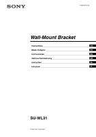
2-636-628-12 (2) Wall-Mount Bracket Instructions GB Mode d'emploi FR Instrucciones ES Gebrauchsanweisung DE Instructies NL Istruzioni IT SU-WL31 © 2005 Sony Corporation - Sony KLV-S32A10 | Instructions (SU-WL31 Wall-Mount Bracket) - Page 2
KDL-V26XBR1 KLV-S32A1s* KLV-S26A1s* KLV-S23A1s* * In the actual model names, the "s" indicates numbers and/or characters specific to each model. This Wall-Mount Bracket is designed for use with the specified products above. For other TVs and monitors, refer to their operating instructions to check - Sony KLV-S32A10 | Instructions (SU-WL31 Wall-Mount Bracket) - Page 3
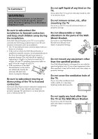
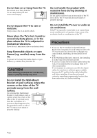
not disassemble or make and keep small children away during alterations to the parts of the Wall- the installation. Mount Bracket. If the Wall-Mount Bracket or the TV is not installed If you do so, the Wall-Mount correctly, the following accidents may occur. Be sure Bracket may fall and cause - Sony KLV-S32A10 | Instructions (SU-WL31 Wall-Mount Bracket) - Page 4
are not observed, injury or property damage may occur. Do not install the Wall-Mount Bracket on wall surfaces where the corners or the sides of the TV protrude away from the wall surface. Do not install the Wall-Mount Bracket on wall surfaces such as a pillar, where the corners or the sides of the - Sony KLV-S32A10 | Instructions (SU-WL31 Wall-Mount Bracket) - Page 5
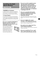
for Sony Dealers only. Be sure to read safety precautions described above and pay special attention to safety during the installation, maintenance and checking of this product. Be sure to install the Wall-Mount Bracket securely to the wall following the instructions in this instruction manual. If - Sony KLV-S32A10 | Instructions (SU-WL31 Wall-Mount Bracket) - Page 6
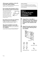
material and structure when mounting the Wall-Mount Bracket. Before installation If your TV is supplied with a leaflet explaining how to install Wall-Mount Bracket ("Installing the Wall-Mount Bracket"), be sure to refer to the leaflet before installation. Step 1: Checking the parts required for the - Sony KLV-S32A10 | Instructions (SU-WL31 Wall-Mount Bracket) - Page 7
Step 2: Changing the position of the arm bases (Except for the TV KDL-S23A1s*/ KLV-S23A1s*) * In the actual model names, the "s" indicates numbers and/or characters specific to each model. If you are installing the TV KDL-S23A1s*/KLVS23A1s*, do not change the position of the arm bases. 1 Remove the - Sony KLV-S32A10 | Instructions (SU-WL31 Wall-Mount Bracket) - Page 8
hole and bore a hole in the wall. WARNING The wall that the TV will be installed on should be capable of supporting a weight of at least four times that of the TV (page 16). Make sure of the strength of the wall the TV will be installed on. Reinforce the wall sufficiently, if necessary. Unit: mm - Sony KLV-S32A10 | Instructions (SU-WL31 Wall-Mount Bracket) - Page 9
the screw used in procedure 1. WARNING The wall that the TV will be installed on should be capable of supporting a weight of at least four times that of the TV (page 16). Make sure of the strength of the wall the TV will be installed on. Reinforce the wall sufficiently, if necessary. 2 1 Plate Unit - Sony KLV-S32A10 | Instructions (SU-WL31 Wall-Mount Bracket) - Page 10
instructions or the leaflet ("Installing the Wall-Mount Bracket") supplied with the TV or monitor. Stabilizer arm Step 5: Preparing for the installation of the TV The procedure differs depending on the TV. Apply the procedure appropriate for the TV you are installing. KDL-V32A1s*/KLV-V32A1s - Sony KLV-S32A10 | Instructions (SU-WL31 Wall-Mount Bracket) - Page 11
to the TV and detach the Table-Top Stand from the TV. AB 3 Remove the screws that hold the hinge cover to the TV and detach the hinge cover from the TV (C D E only). CD These will be used in procedure 2 (C only). C Hinge cover D Hinge cover CDE E Hinge cover 2 Attach the Mounting Hook Units - Sony KLV-S32A10 | Instructions (SU-WL31 Wall-Mount Bracket) - Page 12
the rear side of the TV. For details on connecting the AC power cord and the connecting cable(s), refer to the instruction manual of the TV. When you route the cord and the cable in the wall, feed them through the hole you bored (page 17). E Screw (+PSW5 × L16) Mounting Hook Unit Hole for cable - Sony KLV-S32A10 | Instructions (SU-WL31 Wall-Mount Bracket) - Page 13
Units on to the support shafts of the stabilizer arms. 3 Place the lower hooks of the two Mounting Hook Units so that they touch the front side of the arm bases B. 4 Slightly push the TV toward the Plate Unit and upward, to hitch the lower hooks of the two Mounting Hook Units on to - Sony KLV-S32A10 | Instructions (SU-WL31 Wall-Mount Bracket) - Page 14
• Eight hooks of the Mounting Hook Units are firmly hooked on the four shafts of the stabilizer arms. • The cord and the cable are not completion of the installation for safety. When removing the TV To Sony Dealers 1 Unplug the AC power cord from the wall outlet. 2 Remove the two securing screws on - Sony KLV-S32A10 | Instructions (SU-WL31 Wall-Mount Bracket) - Page 15
210 (8 9⁄32) 245 (9 21⁄32) 270 (10 5⁄8) Specifications Unit: mm (inches) Weight: 3.4 kg (7 lb 8 oz) Design and specifications are subject to change without notice. PLATE UNIT 500 (19 11⁄16) MOUNTING HOOK UNIT 40 (1 9⁄16) 15 (GB) - Sony KLV-S32A10 | Instructions (SU-WL31 Wall-Mount Bracket) - Page 16
actual model names, the "s" indicates numbers and/or characters specific to each model. ** The wall that the TV will be installed on should be capable of supporting a weight of at least four times that of the TV. CAUTION This Wall-Mount Bracket is designed for use with the specified products above - Sony KLV-S32A10 | Instructions (SU-WL31 Wall-Mount Bracket) - Page 17
Wall processing dimensions diagram Unit: mm (inches) 500 (19 11/16) 454 (17 7/8) 430 (16 15/16) 215 (8 15/32) 9-7×40 (9/32 × 1 9/16) Slot hole 14 (9/16) 91 (3 19/32) 148 (5 13/16) 25 25 25 (31/32) (31/32) (31/32) 210 (8 9/32) 25 25 25 (31/32) (31/32) (31/32) φ60 (2 3/8) Hole for cable routing - Sony KLV-S32A10 | Instructions (SU-WL31 Wall-Mount Bracket) - Page 18
être en stock ou de ne plus être fabriqu LCD KDL-V32A1s* KDL-V32XBR1 KLV-V26A1s* KDL-S32A1s* KDL-S26A1s* KDL-S23A1s* KLV-V32A1s* KDL-V26A1s* KDL-V26XBR1 KLV-S32A1s* KLV-S26A1s* KLV support de fixation mural (« Installation du support de fixation mural »). À l'attention des détaillants Sony - Sony KLV-S32A10 | Instructions (SU-WL31 Wall-Mount Bracket) - Page 19
téléviseur peut tomber et causer des blessures FR Français graves comme des hématomes ou des fractures. • Si le mur sur lequel le support de fixation murale est fixé est instable, inégal ou non perpendiculaire au sol, l'appareil risque de tomber et de provoquer des blessures ou des dommages mat - Sony KLV-S32A10 | Instructions (SU-WL31 Wall-Mount Bracket) - Page 20
. ATTENTION Le non-respect des consignes suivantes peut entraîner des blessures ou des dommages matériels. Précautions • Si vous utilisez le téléviseur fixé au support de fixation murale pendant une longue période, le mur situé derrière le téléviseur ou au-dessus de celui-ci peut se décolorer, ou - Sony KLV-S32A10 | Instructions (SU-WL31 Wall-Mount Bracket) - Page 21
Les instructions suivantes concernent les détaillants Sony uniquement. Lisez attentivement les consignes de sécurité ci-dessus et accordez une attention particulière à la sécurité lors de l'installation, de l'entretien et de la vérification de ce produit. Veillez à installer le support de fixation - Sony KLV-S32A10 | Instructions (SU-WL31 Wall-Mount Bracket) - Page 22
au cours de l'installation. Prenez garde à ne pas vous blesser les mains ou les doigts pendant l'installation du support de fixation murale ou du téléviseur. Les vis nécessaires à l'installation du support de fixation murale au mur ne sont pas fournies. Utilisez les vis appropriées selon le matériau - Sony KLV-S32A10 | Instructions (SU-WL31 Wall-Mount Bracket) - Page 23
les noms de modèle réels, « s » indique des chiffres et/ou des caractères propres à chaque modèle. Si vous installez le téléviseur KDL-S23A1s*/ KLV-S23A1s*, ne modifiez pas la position des bases des bras. 1 Retirez les quatre vis de réglage des angles (deux de chaque côté) qui fixent les bras - Sony KLV-S32A10 | Instructions (SU-WL31 Wall-Mount Bracket) - Page 24
câbles à travers la paroi murale, déterminez la position du trou et percez-le. AVERTISSEMENT Le mur sur lequel vous installez le téléviseur doit pouvoir supporter un poids équivalent à au moins quatre fois celui du téléviseur (page 16). Vérifiez la solidité du mur sur lequel vous allez installer le - Sony KLV-S32A10 | Instructions (SU-WL31 Wall-Mount Bracket) - Page 25
plaque 2 Fixez la plaque au mur à l'aide d'au moins quatre vis M6 ou équivalentes (non fournies). 1 Serrez fermement les vis afin que la plaque puisse supporter le poids de l'écran. 2 Serrez la vis utilisée à la procédure 1. AVERTISSEMENT Le mur sur lequel vous installez le téléviseur doit pouvoir - Sony KLV-S32A10 | Instructions (SU-WL31 Wall-Mount Bracket) - Page 26
*/ KDL-V32XBR1 A KDL-V26A1s*/KLV-V26A1s*/ KDL-V26XBR1 B KDL-S32A1s*/KLV-S32A1s C KDL-S26A1s*/KLV-S26A1s D KDL-S23A1s*/KLV-S23A1s E * Dans les noms de modèle réels, « s » indique des chiffres et/ou des caractères propres à chaque modèle. 1 Détachez le support de table du téléviseur. 1 Placez - Sony KLV-S32A10 | Instructions (SU-WL31 Wall-Mount Bracket) - Page 27
de câble de 90 degrés et retirez-le (A B uniquement). AB Support de câble 4 Retirez les quatre vis de fixation du support de table au téléviseur, puis détachez le support de table du téléviseur. AB 3 Retirez les vis de fixation du couvercle de la charnière au téléviseur, puis détachez le couvercle - Sony KLV-S32A10 | Instructions (SU-WL31 Wall-Mount Bracket) - Page 28
B Vis (+PSW5 × L16) C Vis (+PSW5 × L16) Resserrez les deux vis, retirées à l'étape 3 de la procédure 1, dans les trous des deux extrémités. D Vis (+PSW5 × L16) Étape 6 : Installation du téléviseur sur la plaque Barre de crochets de fixation murale AVERTISSEMENT Veillez à terminer l'installation - Sony KLV-S32A10 | Instructions (SU-WL31 Wall-Mount Bracket) - Page 29
et droit des bases des bras B, puis serrez-les temporairement. 2 Accrochez les crochets supérieurs des barres de crochets de fixation sur les axes de support des bras stabilisateurs. 3 Placez les crochets inférieurs des deux barres de crochets de fixation de manière à ce qu'ils touchent la face - Sony KLV-S32A10 | Instructions (SU-WL31 Wall-Mount Bracket) - Page 30
un incendie ou l'électrocution. Pour votre sécurité, vérifiez que l'installation est effectuée complètement. Lors du retrait du téléviseur À l'attention des détaillants Sony 1 Débranchez le cordon d'alimentation CA de la prise murale. 2 Retirez les deux vis de fixation des bases des bras gauche et - Sony KLV-S32A10 | Instructions (SU-WL31 Wall-Mount Bracket) - Page 31
210 (8 9⁄32) 245 (9 21⁄32) 270 (10 5⁄8) Caractéristiques Unité : mm (pouces) Poids : 3,4 kg (7 li. 8 on.) La conception et les spécifications sont sujettes à modification sans préavis. PLAQUE 500 (19 11⁄16) BARRE DE CROCHETS DE FIXATION MURALE 40 (1 9⁄16) 15 (FR) - Sony KLV-S32A10 | Instructions (SU-WL31 Wall-Mount Bracket) - Page 32
32) 14 (9/16) 210 (8 9/32) 14 (9/16) KDL-S26A1s*/KLV-S26A1s*/ KDL-S23A1s*/KLV-S23A1s* A 500 (19 11/16) KDL-V32A1s*/KLV-V32A1s*/KDL-V32XBR1/ KDL-S32A1s*/KLV-S32A1s*/KDL-V26A1s*/ KLV d'emploi pour savoir si vous pouvez utiliser le support de fixation murale. Certains téléviseurs et moniteurs sont - Sony KLV-S32A10 | Instructions (SU-WL31 Wall-Mount Bracket) - Page 33
de fixation au mur Unité : mm (pouces) 500 (19 11/16) 454 (17 7/8) 430 (16 15/16) 215 (8 15/32) 9-7×40 (9/32 × 1 9/16) Fente 14 (9/16) 91 (3 19/32) 148 (5 13/16) 25 25 25 (31/32) (31/32) (31/32) 210 (8 9/32) 25 25 25 (31/32) (31/32) (31/32) φ60 (2 3/8) Trou de passage des câbles 12 - Sony KLV-S32A10 | Instructions (SU-WL31 Wall-Mount Bracket) - Page 34
instalación incorrectas. Entregue este manual al cliente después de la instalación. Seguridad Los productos de Sony están diseñados pensando en KDL-V32A1s* KDL-V32XBR1 KLV-V26A1s* KDL-S32A1s* KDL-S26A1s* KDL-S23A1s* KLV-V32A1s* KDL-V26A1s* KDL-V26XBR1 KLV-S32A1s* KLV-S26A1s* KLV-S23A1s* * En los - Sony KLV-S32A10 | Instructions (SU-WL31 Wall-Mount Bracket) - Page 35
Información para los clientes ADVERTENCIA Si no se tienen en cuenta las siguientes precauciones, existe el peligro de sufrir lesiones graves o incluso de muerte a raíz de un incendio o una descarga eléctrica, o a causa de que el producto vuelque o se caiga. No vierta ningún tipo de líquido sobre el - Sony KLV-S32A10 | Instructions (SU-WL31 Wall-Mount Bracket) - Page 36
daños personales so materiales. No manipule el producto con fuerza excesiva cuando realice su limpieza o mantenimiento. No aplique fuerza excesiva en la parte superior del televisor. Si lo hace, el televisor puede caerse y provocar daños personales o materiales. No instale el televisor encima ni - Sony KLV-S32A10 | Instructions (SU-WL31 Wall-Mount Bracket) - Page 37
para los distribuidores de Sony Las instrucciones siguientes están destinadas únicamente a los distribuidores de Sony. Asegúrese de leer soporte de montaje mural firmemente en la pared siguiendo las instrucciones de este manual. Si alguno de los tornillos queda suelto o se desprende, el soporte de - Sony KLV-S32A10 | Instructions (SU-WL31 Wall-Mount Bracket) - Page 38
Una vez haya instalado correctamente el televisor, fije adecuadamente los cables. Si alguna persona u objeto se enreda con los cables, correrá el peligro de sufrir heridas personales o de dañarse el televisor. Antes de la instalación Si el televisor se suministra con un folleto en el que se explica - Sony KLV-S32A10 | Instructions (SU-WL31 Wall-Mount Bracket) - Page 39
*) * En los nombres de modelo reales, "s" indica los números y/o los carácteres específicos de cada modelo. Si instala el televisor modelo KDL-S23A1s* o KLV-S23A1s*, no cambie la posición de las bases del brazo. 1 Extraiga los cuatro tornillos de ajuste del ángulo (dos en cada lado) que aseguran los - Sony KLV-S32A10 | Instructions (SU-WL31 Wall-Mount Bracket) - Page 40
Paso 3: Decidir la ubicación de instalación 1 Deje un espacio adecuado entre el televisor, el techo y las partes salientes de la pared, como se muestra en el siguiente diagrama y decida la ubicación de la instalación. Sugerencia Consulte la tabla de dimensiones para la - Sony KLV-S32A10 | Instructions (SU-WL31 Wall-Mount Bracket) - Page 41
Paso 4: Instalar la placa en la pared 1 Provisionalmente, fije la placa en la pared utilizando un tornillo. Alinee la placa para nivelarla con el suelo. ADVERTENCIA • El tornillo que se utiliza en este procedimiento no se suministra. • Seleccione un tornillo adecuado según el material y la - Sony KLV-S32A10 | Instructions (SU-WL31 Wall-Mount Bracket) - Page 42
monitor distintos de los especificados en la página 2, consulte el manual de instrucciones o el folleto ("Instalación del soporte de montaje mural -V32A1s*/KLV-V32A1s*/ KDL-V32XBR1 A KDL-V26A1s*/KLV-V26A1s*/ KDL-V26XBR1 B KDL-S32A1s*/KLV-S32A1s C KDL-S26A1s*/KLV-S26A1s D KDL-S23A1s*/KLV-S23A1s - Sony KLV-S32A10 | Instructions (SU-WL31 Wall-Mount Bracket) - Page 43
2 Gire el portacables 90 grados y tire de él hacia fuera (solamente A B). AB Portacables 4 Extraiga los cuatro tornillos que sujetan el soporte de sobremesa al televisor y retire el soporte de sobremesa del aparato. AB 3 Extraiga los tornillos que sujetan la cubierta de la bisagra al televisor y - Sony KLV-S32A10 | Instructions (SU-WL31 Wall-Mount Bracket) - Page 44
alimentación de ca y los cables de conexión a los conectores de la parte posterior del televisor. Para obtener información detallada sobre la conexión del cable alimentación de ca y de los cables de conexión, consulte el manual de instrucciones del televisor. Cuando coloque los cables en la pared, - Sony KLV-S32A10 | Instructions (SU-WL31 Wall-Mount Bracket) - Page 45
ejes de soporte de los brazos estabilizadores. 3 Coloque los ganchos inferiores de los dos ganchos de montaje de forma que queden en contacto con la parte frontal de las bases del brazo B. 4 Empuje el televisor suavemente hacia la placa y hacia arriba para enganchar los ganchos inferiores de los dos - Sony KLV-S32A10 | Instructions (SU-WL31 Wall-Mount Bracket) - Page 46
Confirme que haya finalizado la instalación Para retirar el televisor Información para los distribuidores de Sony Compruebe los puntos siguientes. • Que los ocho ganchos del gancho de montaje estén firmemente enganchados a los cuatro ejes de soporte de los brazos estabilizadores. • Que - Sony KLV-S32A10 | Instructions (SU-WL31 Wall-Mount Bracket) - Page 47
210 (8 9⁄32) 245 (9 21⁄32) 270 (10 5⁄8) Especificaciones Unidad: mm (pulgadas) Peso: 3,4 kg (7 lb 8 oz) Diseño y especificaciones sujetos a cambios sin previo aviso. PLACA 500 (19 11⁄16) GANCHO DE MONTAJE 40 (1 9⁄16) 15 (ES) - Sony KLV-S32A10 | Instructions (SU-WL31 Wall-Mount Bracket) - Page 48
32) 14 (9/16) 210 (8 9/32) 14 (9/16) KDL-S26A1s*/KLV-S26A1s*/ KDL-S23A1s*/KLV-S23A1s* A 500 (19 11/16) KDL-V32A1s*/KLV-V32A1s*/KDL-V32XBR1/ KDL-S32A1s*/KLV-S32A1s*/KDL-V26A1s*/ KLV Con otros televisores y monitores, consulte los manuales de instrucciones correspondientes para comprobar si es - Sony KLV-S32A10 | Instructions (SU-WL31 Wall-Mount Bracket) - Page 49
la pared Unidad: mm (pulgadas) 500 (19 11/16) 454 (17 7/8) 430 (16 15/16) 215 (8 15/32) 9-7×40 (9/32 × 1 9/16) Orificio de ranura 14 (9/16) 91 (3 19/32) 148 (5 13/16) 25 25 25 (31/32) (31/32) (31/32) 210 (8 9/32) 25 25 25 (31/32) (31/32) (31/32) φ60 (2 3/8) Orificio para el paso de cables 12 - Sony KLV-S32A10 | Instructions (SU-WL31 Wall-Mount Bracket) - Page 50
späteren Nachschlagen sorgfältig auf. Sicherheit Bei der Entwicklung von Sony-Produkten wird besonderer Wert auf den Faktor Sicherheit gelegt. Wenn ein V32A1s* KDL-V32XBR1 KLV-V26A1s* KDL-S32A1s* KDL-S26A1s* KDL-S23A1s* KLV-V32A1s* KDL-V26A1s* KDL-V26XBR1 KLV-S32A1s* KLV-S26A1s* KLV-S23A1s* * „s" - Sony KLV-S32A10 | Instructions (SU-WL31 Wall-Mount Bracket) - Page 51
Für den Kunden WARNUNG Bitte beachten Sie unbedingt die folgenden Sicherheitsmaßnahmen! Andernfalls kann es durch Feuer, einen elektrischen Schlag, das Umkippen oder das Herunterfallen des Produkts zu schweren oder gar tödlichen Verletzungen kommen. Lassen Sie die Installationsarbeiten unbedingt von - Sony KLV-S32A10 | Instructions (SU-WL31 Wall-Mount Bracket) - Page 52
Lehnen und hängen Sie sich nicht an das Fernsehgerät. Andernfalls kann das Fernsehgerät auf Sie fallen und schwere Verletzungen verursachen. Schützen Sie das Fernsehgerät vor Regen und Feuchtigkeit. Andernfalls besteht Feuergefahr oder die Gefahr eines elektrischen Schlags. Installieren Sie das - Sony KLV-S32A10 | Instructions (SU-WL31 Wall-Mount Bracket) - Page 53
ändler oder lizenzierten Fachleuten ausführen und beachten Sie bei der Installation die nötigen Sicherheitsvorkehrungen. Für Sony-Händler Die folgenden Anweisungen richten sich ausschließlich an Sony-Händler. Lesen Sie die oben erläuterten Sicherheitsmaßnahmen sorgfältig durch und beachten Sie bei - Sony KLV-S32A10 | Instructions (SU-WL31 Wall-Mount Bracket) - Page 54
Sichern Sie die Kabel ordnungsgemäß, nachdem das Fernsehgerät korrekt installiert wurde. Wenn jemand über die Kabel stolpert oder sich Gegenstände darin verfangen, besteht Verletzungsgefahr oder das Fernsehgerät kann beschädigt werden. Achten Sie darauf, das Netzkabel und die Verbindungskabel nicht - Sony KLV-S32A10 | Instructions (SU-WL31 Wall-Mount Bracket) - Page 55
Schritt 2: Ändern der Position der Armstützen (außer beim Fernsehgerät KDL-S23A1s*/ KLV-S23A1s*) * „s" steht für Zahlen und/oder Zeichen, die im eigentlichen Modellnamen für das jeweilige Modell eindeutig sind. Wenn Sie das Fernsehgerät KDL-S23A1s*/KLVS23A1s* installieren, ändern Sie - Sony KLV-S32A10 | Instructions (SU-WL31 Wall-Mount Bracket) - Page 56
Schritt 3: Festlegen der Montageposition 1 Halten Sie zwischen dem Fernsehgerät und der Decke bzw. vorstehenden Teilen der Wand unbedingt die in der Abbildung unten gezeigten Abstände ein und legen Sie die Montageposition fest. Tipp Näheres dazu finden Sie in Aufriss und Tabelle der - Sony KLV-S32A10 | Instructions (SU-WL31 Wall-Mount Bracket) - Page 57
Schritt 4: Installieren der Montageplatte an der Wand 1 Befestigen Sie die Montageplatte vorübergehend mit einer Schraube an der Wand. Richten Sie die Montageplatte waagrecht aus. ACHTUNG • Die in diesem Schritt verwendete Schraube ist nicht mitgeliefert. • Wählen Sie eine Schraube aus, die für das - Sony KLV-S32A10 | Instructions (SU-WL31 Wall-Mount Bracket) - Page 58
vor, das für das zu installierende Fernsehgerät geeignet ist. KDL-V32A1s*/KLV-V32A1s*/ KDL-V32XBR1 A KDL-V26A1s*/KLV-V26A1s*/ KDL-V26XBR1 B KDL-S32A1s*/KLV-S32A1s C KDL-S26A1s*/KLV-S26A1s D KDL-S23A1s*/KLV-S23A1s E * „s" steht für Zahlen und/oder Zeichen, die im eigentlichen Modellnamen - Sony KLV-S32A10 | Instructions (SU-WL31 Wall-Mount Bracket) - Page 59
2 Drehen Sie den Kabelhalter um 90 Grad und ziehen Sie ihn heraus (nur A B). AB Kabelhalter 4 Entfernen Sie die vier Schrauben, mit denen der Tischständer am Fernsehgerät befestigt ist, und nehmen Sie den Tischständer vom Fernsehgerät ab. AB 3 Entfernen Sie die Schrauben, mit denen die - Sony KLV-S32A10 | Instructions (SU-WL31 Wall-Mount Bracket) - Page 60
B Schraube (+PSW5 × L16) Schritt 6: Installieren des Fernsehgeräts auf der Montageplatte C Schraube (+PSW5 × L16) Ziehen Sie die beiden in Schritt 1 unter 3 entfernten Schrauben in den Bohrungen an den beiden Enden wieder an. D Schraube (+PSW5 × L16) Befestigungsstrebe ACHTUNG Führen Sie erst - Sony KLV-S32A10 | Instructions (SU-WL31 Wall-Mount Bracket) - Page 61
2 Installieren Sie das Fernsehgerät auf der Montageplatte. 1 Setzen Sie die Schrauben (+B5 × L12, mitgeliefert) zum Fixieren der Befestigungsstreben in die Schraublöcher links und rechts außen an den Armstützen B ein und ziehen Sie sie provisorisch an. 2 Hängen Sie die oberen Haken der beiden - Sony KLV-S32A10 | Instructions (SU-WL31 Wall-Mount Bracket) - Page 62
verdreht oder eingeklemmt sind. • Die beiden Befestigungsschrauben an den Armstützen müssen fest angezogen sein. Wenn Sie das Fernsehgerät abnehmen Für Sony-Händler 1 Lösen Sie das Netzkabel von der Netzsteckdose. 2 Entfernen Sie die beiden Befestigungsschrauben an den rechten und linken Armstützen - Sony KLV-S32A10 | Instructions (SU-WL31 Wall-Mount Bracket) - Page 63
270 210 245 Technische Daten Einheit: mm Gewicht: 3,4 kg Änderungen, die dem technischen Fortschritt dienen, bleiben vorbehalten. MONTAGEPLATTE 500 BEFESTIGUNGSSTREBE 40 15 (DE) - Sony KLV-S32A10 | Instructions (SU-WL31 Wall-Mount Bracket) - Page 64
Bildschirmmittellinie Bohrung für vorübergehendes Anbringen der Montageplatte Fernsehmodell KDL-V32A1s* KLV-V32A1s* KDL-V32XBR1 KDL-V26A1s* KLV-V26A1s* KDL-V26XBR1 KDL-S32A1s* KLV-S32A1s* KDL-S26A1s* KLV-S26A1s* KDL-S23A1s* KLV-S23A1s* Abmessungen des Fernsehgeräts A B C D 808 550 111 38 - Sony KLV-S32A10 | Instructions (SU-WL31 Wall-Mount Bracket) - Page 65
Abmessungen für die Bohrungen in der Wand Einheit: mm 500 454 430 215 9-7×40 Bohrung 25 25 25 210 25 25 25 φ60 Aussparung zum Verlegen der Kabel 91 14 12-φ7 148 17 (DE) - Sony KLV-S32A10 | Instructions (SU-WL31 Wall-Mount Bracket) - Page 66
producten houdt Sony rekening met KLV-S32A1s* KLV-S26A1s* KLV-S23A1s* * In de werkelijke modelnamen staan in plaats van "s" nummers en/of letters die voor elk model anders zijn. Deze wandmontagesteun is speciaal geschikt voor gebruik met de hiervoor opgegeven producten. Controleer voor andere tv - Sony KLV-S32A10 | Instructions (SU-WL31 Wall-Mount Bracket) - Page 67
elkaar en pas de onderdelen van de steun niet aan. Als u dit wel doet, kan de de installatie. Als de wandmontagesteun of de tv niet correct wordt geïnstalleerd, kunnen de volgende ongelukken plaatsvinden. Zorg ervoor dat de installatie wordt wandmontagesteun vallen. Dit kan letsel of beschadiging - Sony KLV-S32A10 | Instructions (SU-WL31 Wall-Mount Bracket) - Page 68
door coaxkabels van 75 ohm. Als u toch voedingskabels van 300 ohm moet gebruiken, controleert u vóór de installatie of er voldoende ruimte tussen de tv en de voedingskabels achter de muur is. Voordat de steun wordt geïnstalleerd, moet u contact opnemen met de bevoegde installateur over een geschikte - Sony KLV-S32A10 | Instructions (SU-WL31 Wall-Mount Bracket) - Page 69
de installatie speciale aandacht aan de veiligheid. Voor Sony-handelaars De volgende instructies zijn alleen voor Sonyhandelaars. de schroeven loszit of uit de muur valt, kan de tv vallen. Dit kan lichamelijk letsel of beschadiging van de tv tot gevolg hebben. Draai de schroeven stevig vast op de - Sony KLV-S32A10 | Instructions (SU-WL31 Wall-Mount Bracket) - Page 70
verward in de kabels, dan kan dit letsel of beschadiging van de tv tot gevolg hebben. Zorg ervoor dat het netsnoer en de verbindingskabel niet die geschikt zijn voor het wandmateriaal. 2 Pak de kartonnen doos uit en controleer of de volgende onderdelen aanwezig zijn. Plaat (1) Schroef (+PSW5 × L16 - Sony KLV-S32A10 | Instructions (SU-WL31 Wall-Mount Bracket) - Page 71
*) * In de werkelijke modelnamen staan in plaats van "s" nummers en/of letters die voor elk model anders zijn. Als u de tv's KDL-S23A1s*/KLV-S23A1s* installeert, pas dan de positie van de armsteunen niet aan. 1 Verwijder de vier hoekafstelschroeven (twee aan elke zijde) waarmee de stabilisatiearmen - Sony KLV-S32A10 | Instructions (SU-WL31 Wall-Mount Bracket) - Page 72
en uitstekende onderdelen van de muur, zoals weergegeven in het schema hieronder, en bepaal de installatieplek. Tip Raadpleeg de maattabel voor installatie van de tv op pagina 16. Eenheid: mm 2 Raadpleeg pagina 17 en bepaal de posities van de schroeven. Als u de kabels door de muur wilt geleiden - Sony KLV-S32A10 | Instructions (SU-WL31 Wall-Mount Bracket) - Page 73
de plaat het gewicht van het scherm kan dragen. 2 Draai de schroeven die zijn gebruikt in procedure 1, vast. WAARSCHUWING De muur waaraan de tv wordt geïnstalleerd, moet geschikt zijn om ten minste viermaal het gewicht van de tv te dragen (pagina 16). Vergewis u van de sterkte van de muur waaraan de - Sony KLV-S32A10 | Instructions (SU-WL31 Wall-Mount Bracket) - Page 74
u de tv loodrecht plaatst (0 graden), is aanpassing van de hoek van de armen (stap 1 en 2 hierna) niet nodig. Controleer of elke tv die u installeert. KDL-V32A1s*/KLV-V32A1s*/ KDL-V32XBR1 A KDL-V26A1s*/KLV-V26A1s*/ KDL-V26XBR1 B KDL-S32A1s*/KLV-S32A1s C KDL-S26A1s*/KLV-S26A1s D KDL-S23A1s*/KLV- - Sony KLV-S32A10 | Instructions (SU-WL31 Wall-Mount Bracket) - Page 75
eruit (alleen A B). AB Kabelhouder 4 Verwijder de vier schroeven waarmee de tafelbladstandaard aan de tv is vastgemaakt, en maak de tafelbladstandaard van de tv los. AB 3 Verwijder de schroeven waarmee de scharnierafdekking aan de tv is vastgemaakt, en maak de scharnierafdekking los van de - Sony KLV-S32A10 | Instructions (SU-WL31 Wall-Mount Bracket) - Page 76
aan. Sluit het wisselstroomsnoer en de aansluitkabel(s) aan op de contrastekkers aan de achterkant van de tv. Raadpleeg de handleiding van de tv voor meer informatie over aansluiting van het wisselstroomsnoer en de aansluitkabel(s). Als u het snoer en de kabel door de muur voert, schuif ze dan door - Sony KLV-S32A10 | Instructions (SU-WL31 Wall-Mount Bracket) - Page 77
zodanig dat ze de voorkant van de armsteunen B raken. 4 Duw de tv enigszins richting de plaat en omhoog om de onderste montagehaken aan de armsteunen de armsteunen uitsteken, passen de onderste montagehaken niet. 4 3 5 Controleer of de acht haken stevig zijn vastgemaakt aan de vier schachten van - Sony KLV-S32A10 | Instructions (SU-WL31 Wall-Mount Bracket) - Page 78
Voltooiing van de installatie controleren De tv verwijderen Voor Sony-handelaars Controleer de volgende punten. • Acht montagehaken zijn stevig vastgemaakt aan de vier schachten van de stabilisatiearmen. • Het snoer en de kabel zijn niet ineengedraaid en zitten - Sony KLV-S32A10 | Instructions (SU-WL31 Wall-Mount Bracket) - Page 79
270 210 245 Specificaties Eenheid: mm Gewicht: 3,4 kg Ontwerp en specificaties zijn onderhevig aan wijzigingen zonder voorafgaande kennisgeving. PLAAT 500 MONTAGEHAKEN 40 15 (NL) - Sony KLV-S32A10 | Instructions (SU-WL31 Wall-Mount Bracket) - Page 80
*/KDL-V26XBR1 A F 500 DB E D C G B E B H Middellijn van scherm Gat gebruikt voor het tijdelijk vastmaken van de plaat Tv-model KDL-V32A1s* KLV-V32A1s* KDL-V32XBR1 Afmetingen van de tv A B C 808 550 111 KDL-V26A1s* KLV-V26A1s* 675 473 103 KDL-V26XBR1 KDL-S32A1s* 792 564 99 - Sony KLV-S32A10 | Instructions (SU-WL31 Wall-Mount Bracket) - Page 81
Maatschema voor wandbewerking Eenheid: mm 500 454 430 215 9-7×40 Gleufopening 25 25 25 210 25 25 25 φ60 Gat voor kabelgeleiding 91 14 12-φ7 148 17 (NL) - Sony KLV-S32A10 | Instructions (SU-WL31 Wall-Mount Bracket) - Page 82
colori LCD KDL-V32A1s* KDL-V32XBR1 KLV-V26A1s* KDL-S32A1s* KDL-S26A1s* KDL-S23A1s* KLV-V32A1s* KDL-V26A1s* KDL-V26XBR1 KLV-S32A1s* KLV-S26A1s* KLV-S23A1s* Leggere con attenzione il presente manuale delle istruzioni per garantire la sicurezza durante l'installazione. Sony non può essere ritenuta - Sony KLV-S32A10 | Instructions (SU-WL31 Wall-Mount Bracket) - Page 83
Per i clienti Non versare liquidi di alcun tipo sul televisore. ATTENZIONE Se il televisore dovesse bagnarsi, potrebbero generarsi incendi o scosse elettriche. Se le precauzioni riportate di seguito non vengono rispettate, è possibile procurarsi ferite Dopo aver completato il montaggio gravi o - Sony KLV-S32A10 | Instructions (SU-WL31 Wall-Mount Bracket) - Page 84
. Non esercitare una pressione eccessiva sul prodotto durante le operazioni di pulizia e manutenzione. Non applicare una pressione eccessiva sulla parte superiore del televisore. Diversamente, è possibile che il televisore cada e provochi ferite o danni a oggetti. Non installare il televisore sopra - Sony KLV-S32A10 | Instructions (SU-WL31 Wall-Mount Bracket) - Page 85
. Per gli installatori Sony Le seguenti istruzioni sono rivolte esclusivamente agli installatori Sony. Assicurarsi di leggere staffa di montaggio a parete in modo saldo seguendo le istruzioni riportate nel presente manuale. Se le viti non sono serrate in modo saldo o fuoriescono, è possibile - Sony KLV-S32A10 | Instructions (SU-WL31 Wall-Mount Bracket) - Page 86
Dopo aver installato correttamente il televisore, fissare i cavi in modo saldo. Se i cavi dovessero costituire un ostacolo per le persone o gli oggetti, potrebbero verificarsi ferite o danni. Prestare attenzione affinché il cavo di alimentazione CA o il cavo di collegamento non rimangano incastrati. - Sony KLV-S32A10 | Instructions (SU-WL31 Wall-Mount Bracket) - Page 87
2: Modifica della posizione delle basi dei bracci (eccetto TV KDL-S23A1s*/ KLV-S23A1s*) * Nei nomi dei modelli, "s" indica numeri e/o caratteri utilizzati per designare i singoli modelli. Se si sta installando un televisore KDL-S23A1s*/ KLV-S23A1s*, si raccomanda di non modificare la posizione delle - Sony KLV-S32A10 | Instructions (SU-WL31 Wall-Mount Bracket) - Page 88
Punto 3: Individuazione del luogo di installazione 1 Assicurarsi che la distanza tra il televisore e il soffitto e le parti sporgenti della parete corrisponda a quanto indicato nello schema sottostante. Suggerimento Fare riferimento alla tabella con le dimensioni di installazione riportata a pagina - Sony KLV-S32A10 | Instructions (SU-WL31 Wall-Mount Bracket) - Page 89
Punto 4: Installazione della piastra sulla parete 1 Fissare temporaneamente la piastra alla parete per mezzo di una vite. Posizionare correttamente la piastra in modo che risulti in piano. ATTENZIONE • La vite utilizzata in questa procedura non è fornita in dotazione. • Utilizzare una vite - Sony KLV-S32A10 | Instructions (SU-WL31 Wall-Mount Bracket) - Page 90
la procedura adatta al modello che si sta installando. KDL-V32A1s*/KLV-V32A1s*/ KDL-V32XBR1 A KDL-V26A1s*/KLV-V26A1s*/ KDL-V26XBR1 B KDL-S32A1s*/KLV-S32A1s C KDL-S26A1s*/KLV-S26A1s D KDL-S23A1s*/KLV-S23A1s E * Nei nomi dei modelli, "s" indica numeri e/o caratteri utilizzati per designare - Sony KLV-S32A10 | Instructions (SU-WL31 Wall-Mount Bracket) - Page 91
2 Ruotare il fermacavo di 90°, quindi estrarlo (solo A B). AB Fermacavo 4 Rimuovere le quattro viti utilizzate per fissare il supporto da tavolo al televisore; quindi staccare il supporto da tavolo dal televisore. AB 3 Rimuovere le viti utilizzate per fissare il copricerniera al televisore; quindi - Sony KLV-S32A10 | Instructions (SU-WL31 Wall-Mount Bracket) - Page 92
di alimentazione e i cavi di collegamento ai connettori presenti sulla parte posteriore del televisore. Per maggiori dettagli sul collegamento al televisore del cavo di alimentazione o dei cavi di collegamento, consultare il manuale d'istruzioni del televisore. Se si desidera far passare il cavo - Sony KLV-S32A10 | Instructions (SU-WL31 Wall-Mount Bracket) - Page 93
2 Installare il televisore sulla piastra. 1 Inserire le viti (+B5 × L12, in dotazione) per il fissaggio del supporto di montaggio nei fori presenti sui lati esterni sinistro e destro delle basi dei bracci B, quindi stringerle temporaneamente. 2 Agganciare i ganci superiori dei due supporti di - Sony KLV-S32A10 | Instructions (SU-WL31 Wall-Mount Bracket) - Page 94
Verifica del completamento dell'installazione Rimozione del televisore Per gli installatori Sony Verificare quanto segue. • Gli otto ganci dei supporti di montaggio sono saldamente agganciati sui quattro perni dei bracci stabilizzatori. • Il cavo di alimentazione e il cavo - Sony KLV-S32A10 | Instructions (SU-WL31 Wall-Mount Bracket) - Page 95
270 210 245 Caratteristiche tecniche Unità di misura: mm Peso: 3,4 kg Le caratteristiche e specifiche sono soggette a modifiche senza preavviso. PIASTRA 500 SUPPORTO DI MONTAGGIO 40 15 (IT) - Sony KLV-S32A10 | Instructions (SU-WL31 Wall-Mount Bracket) - Page 96
Foro utilizzato per l'installazione temporanea della piastra Modello del televisore KDL-V32A1s* KLV-V32A1s* KDL-V32XBR1 KDL-V26A1s* KLV-V26A1s* KDL-V26XBR1 KDL-S32A1s* KLV-S32A1s* KDL-S26A1s* KLV-S26A1s* KDL-S23A1s* KLV-S23A1s* Dimensioni del televisore A B C 808 550 111 675 473 103 792 - Sony KLV-S32A10 | Instructions (SU-WL31 Wall-Mount Bracket) - Page 97
Diagramma delle dimensioni per l'applicazione a parete Unità di misura: mm 500 454 430 215 9-7×40 Foro a incastro 25 25 25 210 25 25 25 φ60 Foro per i cavi 91 14 12-φ7 148 17 (IT) - Sony KLV-S32A10 | Instructions (SU-WL31 Wall-Mount Bracket) - Page 98
- Sony KLV-S32A10 | Instructions (SU-WL31 Wall-Mount Bracket) - Page 99
- Sony KLV-S32A10 | Instructions (SU-WL31 Wall-Mount Bracket) - Page 100
Printed in Japan
-
 1
1 -
 2
2 -
 3
3 -
 4
4 -
 5
5 -
 6
6 -
 7
7 -
8
-
9
-
10
-
11
-
12
-
13
-
14
-
15
-
16
-
17
-
18
-
19
-
20
-
21
-
22
-
23
-
24
-
25
-
26
-
27
-
28
-
29
-
30
-
31
-
32
-
33
-
34
-
35
-
36
-
37
-
38
-
39
-
40
-
41
-
42
-
43
-
44
-
45
-
46
-
47
-
48
-
49
-
50
-
51
-
52
-
53
-
54
-
55
-
56
-
57
-
58
-
59
-
60
-
61
-
62
-
63
-
64
-
65
-
66
-
67
-
68
-
69
-
70
-
71
-
72
-
73
-
74
-
75
-
76
-
77
-
78
-
79
-
80
-
81
-
82
-
83
-
84
-
85
-
86
-
87
-
88
-
89
-
90
-
91
-
92
-
93
-
94
-
95
-
96
-
97
-
98
-
99
-
100
 |
 |
© 2005 Sony Corporation
2-636-628-
12
(2)
SU-WL31
Wall-Mount Bracket
Instructions
Mode d’emploi
Instrucciones
Gebrauchsanweisung
Instructies
Istruzioni
GB
DE
ES
NL
IT
FR