Sony MFM-HT75W User Manual - Page 7
Rear of the LCD display - power supply
 |
View all Sony MFM-HT75W manuals
Add to My Manuals
Save this manual to your list of manuals |
Page 7 highlights
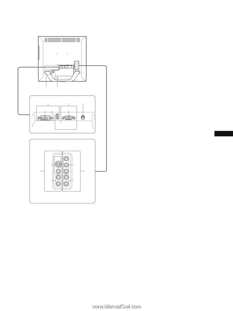
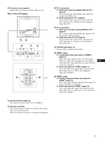
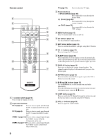
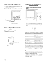
M Connector cover (page 9) Remove this cover when you connect cables or cords. Rear of the LCD display qf qg qh 12 qj qk 1 PC 1 2 PC 2 VHF/UHF VIDEO 2 IN VIDEO 1 IN 1 ql 1 w; 2 2 P PC 1 connectors 1 DVI-D input connector (digital RGB) for PC 1 (page 9) This connector inputs digital RGB video signals that comply with DVI Rev.1.0. 2 Audio input jack for PC 1 (page 9) This jack inputs audio signals when connected to the audio output jack of a computer or other equipment connected to PC 1. Q PC 2 connectors 1 HD15 input connector (analog RGB) for PC 2 (page 9) This connector inputs analog RGB video signals (0.700 Vp-p, positive) and sync signals. 2 Audio input jack for PC 2 (page 9) This jack inputs audio signals when connected to the audio output jack of a computer or other equipment connected to PC 2. R VHF/UHF jack (page 11) This jack inputs a signal from an antenna. S VIDEO 2 jacks 1 Composite/S video input jacks for VIDEO 2 (page 11) These jacks input composite video or S video signals. When you connect video equipment to both composite US video input and S video input jacks, the signal from the S video jack is displayed. 2 Audio input jacks for VIDEO 2 (page 11) These jacks input audio signals when connected to the audio output jacks of a VCR or other equipment connected to VIDEO 2. T VIDEO 1 jacks 1 Y/PB/PR Component Video input jacks for VIDEO 1 (page 10) These jacks input Y/PB/PR Component Video signals (Y/ CB/CR, Y/B-Y/R-Y, or Y/PB/PR). 2 Audio input jacks for VIDEO 1 (page 10) These jacks input audio signals when connected to the audio output jacks of a DVD player or other equipment connected to VIDEO 1. N AC IN connector (page 12) This connector connects the power cord (supplied). O Security Lock Hole The security lock hole should be used with the Kensington Micro Saver Security System. Micro Saver Security System is a trademark of Kensington. 7
-
 1
1 -
 2
2 -
 3
3 -
 4
4 -
 5
5 -
 6
6 -
 7
7 -
 8
8 -
 9
9 -
 10
10 -
 11
11 -
 12
12 -
13
-
14
-
15
-
16
-
17
-
18
-
19
-
20
-
21
-
22
-
23
-
24
-
25
-
26
-
27
-
28
-
29
-
30
-
31
-
32
-
33
-
34
-
35
-
36
-
37
-
38
-
39
-
40
-
41
 |
 |