Sony MFM-HT75W User Manual - Page 9
Setup - lcd
 |
View all Sony MFM-HT75W manuals
Add to My Manuals
Save this manual to your list of manuals |
Page 9 highlights
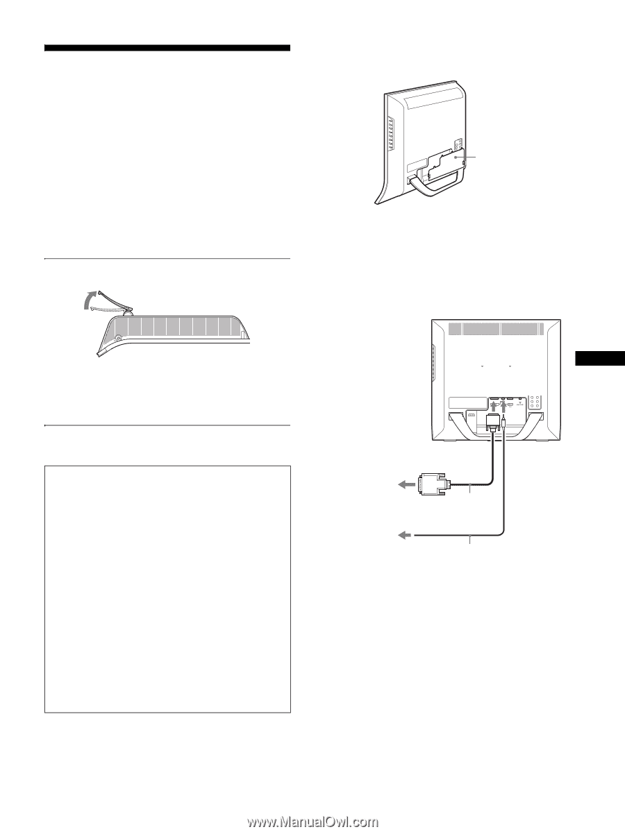
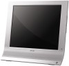
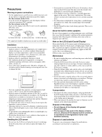
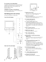
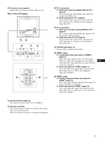
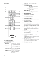
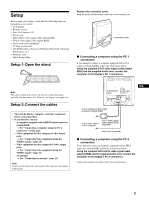
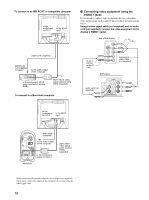
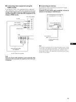
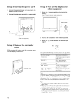
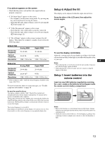
Setup Before using your display, check that the following items are included in your carton: • LCD display • Remote control • Size AAA batteries (2) • Power cord • HD15-HD15 video signal cable (analog RGB) • DVI-D video signal cable (digital RGB) • Audio cord (stereo miniplug) • 75-ohm coaxial cable • CD-ROM (utility software for Windows/Macintosh, Operating Instructions, etc.) • Warranty card • Quick Setup Guide Setup 1: Open the stand Remove the connector cover. Push the hooks and draw the connector cover towards you. connector cover x Connecting a computer using the PC 1 connectors If you intend to connect a computer equipped with a DVI connector (digital RGB), follow the instructions below. Using the supplied DVI-D video signal cable (digital RGB) and the supplied audio cord, connect the computer to the display's PC 1 connectors. Note The stand is folded at the factory. Be sure not to place the display vertically with the stand as it is. Otherwise, the display may topple over. Setup 2: Connect the cables • Turn off the display, computer, and other equipment before connecting them. • If you intend to connect: - A computer equipped with an HD15 output connector (analog RGB) t See "Connecting a computer using the PC 2 connectors" on this page. - Video equipment that has component video output jacks t See "Connecting video equipment using the VIDEO 1 jacks" (page 10). - Video equipment that has composite/S video output jacks t See "Connecting video equipment using the VIDEO 2 jacks" (page 11). - An antenna t See "Connecting an antenna" (page 11). Note Do not touch the pins of the video signal cable connector as this might bend the pins. to the to the DVI-D audio input input for PC 1 US to the computer's DVI output connector (digital RGB) to the audio output of the computer DVI-D video signal cable (digital RGB) (supplied) audio cord (supplied) x Connecting a computer using the PC 2 connectors If you intend to connect a computer equipped with an HD15 connector (analog RGB), follow the instructions below. Using the supplied HD15-HD15 video signal cable (analog RGB) and the supplied audio cord, connect the computer to the display's PC 2 connectors. Connect the computer according to the following illustrations. 9
-
 1
1 -
2
-
3
-
 4
4 -
 5
5 -
 6
6 -
 7
7 -
 8
8 -
 9
9 -
 10
10 -
 11
11 -
 12
12 -
 13
13 -
 14
14 -
15
-
16
-
17
-
18
-
19
-
20
-
21
-
22
-
23
-
24
-
25
-
26
-
27
-
28
-
29
-
30
-
31
-
32
-
33
-
34
-
35
-
36
-
37
-
38
-
39
-
40
-
41
 |
 |