Sony MZ-R900 Service Manual
Sony MZ-R900 Manual
 |
View all Sony MZ-R900 manuals
Add to My Manuals
Save this manual to your list of manuals |
Sony MZ-R900 manual content summary:
- Sony MZ-R900 | Service Manual - Page 1
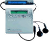
SERVICE MANUAL Ver 1.2 2001. 03 Photo: Red type MZ-R900 US Model Canadian Model AEP Model record, use a fully charged rechargeable battery. Recording time may differ according to the alkaline batteries. - Continued on next page - PORTABLE MINIDISC RECORDER 9-927-991-13 2001C0500-1 C 2001.3 Sony - Sony MZ-R900 | Service Manual - Page 2
MZ-R900 3) Measured in accordance with the EIAJ(Electronic Industries Association of Japan) standard. 4) When using a 100% fully charged rechargeable battery. 5) When using a Sony LR6 (SG) "STAMINA" alkaline dry battery (produced in Japan). When playing (Unit: approx.hours)(EIAJ1)) Batteries - Sony MZ-R900 | Service Manual - Page 3
SERVICING NOTES MZ-R900 NOTES ON HANDLING THE OPTICAL PICK-UP BLOCK OR BASE UNIT The laser diode in the optical pick-up block may suffer electrostatic break-down because of the potential difference generated by the charged some adjusted values were set in the manual mode at the shipment, but these - Sony MZ-R900 | Service Manual - Page 4
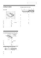
MZ-R900 SECTION 2 GENERAL This section is extracted from instruction manual. Looking at controls See pages in ( ) for more details. The recorder 1 qa 2 qs 3 4 qd 5 qf 6 qg 7 qh qj 8 qk 9 ql q; w; A END SEARCH button (17) (47) B Battery of the remote control A B CD E F - Sony MZ-R900 | Service Manual - Page 5
SECTION 3 DISASSEMBLY MZ-R900 3-2. PANEL ASSY, BOTTOM 3-3. PANEL ASSY, UPPER SECTION 3-5. MAIN BOARD ASSY 3-4. "LCD MODULE", "PANEL ASSY, UPPER" 3-6. "CASE ASSY, BATTERY", "MAIN BOARD" 3-7. STRIP, ORNAMENTAL 3-8. "MD MECHANISM DECK (MT-MZR900-171)", "CHASSIS ASSY, SET" 3-9. SERVICE ASSY, OP - Sony MZ-R900 | Service Manual - Page 6
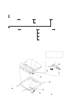
MZ-R900 3-3. PANEL ASSY, UPPER SECTION 3 two screws (1.4) 4 panel assy, upper section 1 flexible board (CN801) 3 two screws (1.4) 2 Push button (open). 3-4. "LCD MODULE", "PANEL ASSY, UPPER" 1 four screws (1.7) 2 - Sony MZ-R900 | Service Manual - Page 7
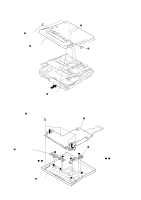
3-5. MAIN BOARD ASSY MZ-R900 6 flexible board (CN501) 5 7 main board assy 1 Remove two solders of flexible board. 3 four screws (M1.4 toothed lock) 4 screw (1.4) 3-6. "CASE ASSY, BATTERY", "MAIN BOARD" 2 flexible board (CN502) 2 case assy, battery 3 main board 1 Remove the solder of - Sony MZ-R900 | Service Manual - Page 8
MZ-R900 3-7. STRIP, ORNAMENTAL 5 Remove the "strip, ornamental" in the direction of 4 two convex portions pointed with @ a boss b boss 3-8. "MD MECHANISM DECK (MT-MZR900-171)", "CHASSIS ASSY, SET" 2 boss 3 MD mechanism deck (MT-MZR900-171) 1 screw (1.4) 2 boss 4 spring (arm), tension 5 - Sony MZ-R900 | Service Manual - Page 9
MZ-R900 3-9. SERVICE ASSY, OP (LCX-4R) 1 washer (0.8-2.5) 3 screw (M1.4) 4 spring (S), rack 5 screw 2 gear (SA) 6 screw (M1.4) 7 spring, thrust 9 Pull off "screw, lead" 8 0 bearing (N) qa Opening the over write head toward the direction A, remove the "service assy, OP (LCX-4R) toward the - Sony MZ-R900 | Service Manual - Page 10
MZ-R900 3-10. HOLDER ASSY 5 Remove the holder assy in the direction of arrow D. 1 Open the holder assy. A D B 2 Push the convex portion toward the direction B and open - Sony MZ-R900 | Service Manual - Page 11
3-12. MOTOR, DC (SLED) (M602) 4 two screws (M1.4) 5 motor, DC (sled) (M602) MZ-R900 1 Remove four solders of motor flexible board. 2 washer (0.8-2.5) 3 gear (SA) 3-13. "MOTOR, DC (SPINDLE) (M601)", "MOTOR, DC (OVER WRITE HEAD UP/DOWN) (M603)" 1 Remove six - Sony MZ-R900 | Service Manual - Page 12
MZ-R900 SECTION 4 TEST MODE Outline • This set provides the Overall adjustment mode that allows CD and MO discs to be automatically adjusted when in the test mode. In this overall adjustment mode, the disc is discriminate between CD and MO, and each adjustment is automatically executed in order. - Sony MZ-R900 | Service Manual - Page 13
Offset Adjustment] Power Supply Adjustment Auto Item Feed CD Overall Adjustment/ MO Overall Adjustment Press the [JOG LEVER $L% R] (up) key, or [DISPLAY] key on the remote commander [Self-Diagnosis Result Display Mode] Press the x key Press the N or [REC] key [Sound Skip Check Result Display Mode - Sony MZ-R900 | Service Manual - Page 14
MZ-R900 5. The display changes a shown below each time the [JOG LEVER $L% R] (up) key or [DISPLAY] key on the remote commander is pressed. • Address & Adjusted Value Display Remote occurred. Clear both self-diagnosis history data and total recording time, if the optical pickup was replaced. • Self - Sony MZ-R900 | Service Manual - Page 15
MZ-R900 • Description of Error Indication Codes Problem TOC error 12 Data reading error 22 Low battery 31 Offset error 32 Focus error ABCD offset last. Two errors before the last. Total recording time Reset the error display code After servicing, reset the error display code. • Setting - Sony MZ-R900 | Service Manual - Page 16
MZ-R900 Sound Skip Check Result Display Mode This set can display the count of errors that occurred during the recording/playing for checking. • Setting method of sound skip check result display mode 1. Set the test mode (see page 12). 2. Press the N key or [REC] key, and the playing or recording - Sony MZ-R900 | Service Manual - Page 17
5 ELECTRICAL ADJUSTMENTS MZ-R900 Outline • In this set, automatic adjustment of CD and MO can be per- formed by entering the test mode (see page 12). However, before starting automatic adjustment, the memory clear, power supply adjustment, and laser power check must be performed in the manual mode - Sony MZ-R900 | Service Manual - Page 18
MZ-R900 7) Select the manual mode of the test mode, and set item number 871 (see page 13). Remote commander LCD display 871 V5num ** **:Adjusted value 8) Adjust with the [VOL+] key (adjusted value up) or [VOL--] key (adjusted value down) so that the adjusted - Sony MZ-R900 | Service Manual - Page 19
MZ-R900 2. When press the X key to write the adjusted value, LCD displays as follows and power supply manual adjustment has completed. Remote meter 7. Press the N key, and set the laser CD read adjustment mode (item number 012). Remote commander LCD display 012 HrefPw ** 8. Check that the laser - Sony MZ-R900 | Service Manual - Page 20
MZ-R900 Overall Adjustment Mode • Configuration of overall adjustment Overall adjustment mode . key (Title display) N key Protect switch ON CD overall adjusting All item OK NG item exists or x key x key CD overall adjustment NG x key Protect switch OFF CD overall adjustment OK N key > key - Sony MZ-R900 | Service Manual - Page 21
MZ-R900 • Adjustment Method of Overall CD and MO Adjustment Mode 1. Setting the test mode (see page 12). 2. Press the . or [VOL --] key activates the overall adjust- ment mode. Remote commander LCD display 000 Assy11 3. Insert CD disc in the set, and press the . key to set the Overall CD Adjustment - Sony MZ-R900 | Service Manual - Page 22
MZ-R900 Resume Clear Perform the Resume clear when all adjustments completed. • Resume Clear Setting Method 1. Select the manual mode of the test mode, and set item number 043 (see page 13). Remote commander LCD display 043 Resume CC 2. Press the X key. Remote commander LCD display 043 Res*** - Sony MZ-R900 | Service Manual - Page 23
MZ-R900 20. Press the [VOL+] key once to change the blinking portion to 0D60. Remote commander LCD display 023 0D6000 00: Data Writing Method (version 1.100) 1. Select the manual mode of the test mode, and set item number 022 (see page 13). Remote commander LCD display 022 PatClr CC 2. Press the - Sony MZ-R900 | Service Manual - Page 24
MZ-R900 8. Press the x key. (00 is blinking) 9. Adjust with the [VOL+] key (adjusted value up) or [VOL--] key (adjusted value down) so that the adjusted value becomes AA. Remote commander LCD display 023 0D5DAA AA:Adjusted value 10. Press the X key. (0D5D is blinking) 11. Press the [VOL+] key once - Sony MZ-R900 | Service Manual - Page 25
MZ-R900 37. Adjust with the [VOL+] key (adjusted value up) or [VOL--] key (adjusted value down) so that the adjusted value becomes 09. Remote or [VOL--] key (adjusted value down) so that the adjusted value becomes 03. Remote commander LCD display 023 0D6E03 03:Adjusted value 50. Press the X key. ( - Sony MZ-R900 | Service Manual - Page 26
MZ-R900 65. Adjust with the [VOL+] key (adjusted value up) or [VOL--] key (adjusted value down) so that the adjusted value becomes 1C. Remote commander 1.200 and later) 1. Select the manual mode of the test mode, and set item number 022 (see page 13). Remote commander LCD display 022 PatClr CC 2. - Sony MZ-R900 | Service Manual - Page 27
M602 (SLED) M M601 W (SPINDLE) U V MZ-R900 M603 OVER WRITE HEAD M UP/DOWN 37 RFI 44 37 VRECIN1 42 C1H CHARGE 28 PUMP 1 C1L 27 C2H CHARGE 31 PUMP 2 C2L CPWO CPVO CPUO 55 56 1 • SIGNAL PATH : PLAYBACK : REC (ANALOG IN) : REC (DIGITAL IN) EFMD 105 DIN1 62 ADDT 68 DADT 67 DIN1 - Sony MZ-R900 | Service Manual - Page 28
MZ-R900 6-2. BLOCK DIAGRAM - AUDIO Section - (Page 27) A DIN1 VIF B+ B+ SWITCH Q302 OPTICAL RECEIVER J301 LINE IN (OPT) (LINE IN JACK) ADDT (Page 27) 142 TSB SLVI 144 TSB SLVO 145 TSB SLAVE DETECT Q803 RMC KEY F (Page 29) • SIGNAL PATH : PLAYBACK : REC (ANALOG IN) : REC (DIGITAL IN) 28 28 - Sony MZ-R900 | Service Manual - Page 29
236 SLEEP 235 VLON 234 WK DET 17 REC KEY 18 HALF LOCK SW 19 SYSTEM CONTROLLER IC801 (3/3) RF AMP (IC501), MOTOR/COIL DRIVER (IC551), REMOTE CONTROL CIRCUIT B+ NOISE FILTER NOISE FILTER L801 L904 51 BATTERY CHARGER & REGULATOR RF2 49 INM2 48 INP2 47 RS 46 CHARGE CONTROL CHG SW 45 CHARGE MONITOR - Sony MZ-R900 | Service Manual - Page 30
, 50 ns/DIV 352 ns w; IC901 th (CLK) 500 mV/DIV, 2 µs/DIV Approx. 35 mVp-p Approx. 1.3 Vp-p 2.5 Vp-p 1 Vp-p 29 88.5 ns 29 29 5.68 µs MZ-R900 - Sony MZ-R900 | Service Manual - Page 31
MZ-R900 3 A B MAIN BOARD (COMPONENT SIDE) C S802 SYNCHRO REC ON T OFF D E (CHASSIS) R845 R840 R838 R817 BATTERY (NICKEL-METAL) NH-14WM 1.2V 1400mAh S801 HOLD HOLD T OFF S804 BATTERY RB801 11 1-679-610- (11) 30 30 IC302 MD MECHANISM C340 C330 R302 R307 R317 C211 R212 R211 C111 - Sony MZ-R900 | Service Manual - Page 32
6-5. SCHEMATIC DIAGRAM • See page 33 for Waveforms. • See page 43 for IC Block Diagrams MZ-R900 31 31 31 31 31 31 - Sony MZ-R900 | Service Manual - Page 33
HP/L MUTE BEEP GA R MZ-R900 • IC Block Diagrams IC301 AK4562VNS-L CDTI LRCK MCLK TST BCLK SDTI SDTO 21 20 19 18 17 16 15 Wpp FE ABCD APC ADIP RF PEAK/BOTM 42 FE 41 ABCD 40 OFC-C1 39 OFC-C2 38 AVCC 37 PS 36 LP 35 EQ 34 AGND 33 RF 32 CCSL2 31 VC 30 VREF075 29 PEAK 28 BOTM OF TRK T-ON 27 DGND 26 - Sony MZ-R900 | Service Manual - Page 34
34 33 32 31 30 VG3 29 VGC VC VG DC IN CHARGE MONITOR X2/X4 DC IN CHARGE CONTROL DC IN OUTPUT SW HI-BRIDGE PRE DRIVER CONTROL VG VG2 VG3 CONTROL CHARGE PUMP 2 VC2 VG CHARGE PUMP 1 VC VREF BUFFER 28 C1H 27 C1L VC2 26 VC2 25 VREF 24 CVREF 23 GND 22 DW BT 21 DW TP BATTERY CHARGER & REGULATOR - Sony MZ-R900 | Service Manual - Page 35
MZ-R900 6-6. IC PIN FUNCTION DESCRIPTION • IC501 SN761057DBT (RF AMP, FOCUS/TRACKING ERROR AMP) Pin No. 1 2 3 4 PD-I PD-O ADFG DVDD SBUS SCK RESET OFTRK DGND BOTM PEAK VREF075 VC CCSL2 RF OUT AGND EQ, LP, PS AGND OFC2, OFC-1 ABCD FE S-MON ADIP-IN - Connect terminal to the external capacitor for - Sony MZ-R900 | Service Manual - Page 36
MZ-R900 input) 11 CHG MON I Charge voltage monitor input terminal (A/D REC key input terminal (A/D input) 19 HALF LOCK SW I Open button detection switch (S805) input terminal (A/D input) "L": when normal position, "H": when locked 20 RMC KEY I Key input terminal (A/D input) of the remote - Sony MZ-R900 | Service Manual - Page 37
MZ-R900 Description I Focus error signal input from RF amp (IC501) I Support signal (I3 signal/temperature signal) input terminal (A/D input) I .5792MHz (fixed at "L" in this set) I Input terminal of the record system digital audio signal O Output terminal of the playback system digital audio - Sony MZ-R900 | Service Manual - Page 38
MZ-R900 Pin No. Pin SENS) monitor output terminal Not used (open) 111 TX O Record data output enable signal output monitor terminal of the internal DSP 8V) 142 RMC DTCK I/O TSB serial data input/output with the remote commander attached headphone 143 TSB SLV VDD - Power supply terminal (for - Sony MZ-R900 | Service Manual - Page 39
MZ-R900 PWM O PWM signal output for the spindle support to the motor driver (IC551) 167, 168 Battery pack detection switch (S804) input terminal for the charge "L": there is battery pack for the charge drive (IC601) 202 REC WBL SW O LPF changeover switch input terminal when REC/PB control Not used - Sony MZ-R900 | Service Manual - Page 40
MZ-R900 Pin No. Pin Name I/O Description 204 XPD ADA O Power supply control signal output for REC switch (S802) input terminal "L": OFF, "H": ON 229 NC O Not used (open) 230 PROTECT I Detection input terminal of the record check claw from the protect detection switch (S803) "L": recording - Sony MZ-R900 | Service Manual - Page 41
required for routine service. Some delay should be anticipated when ordering these items. • The mechanical parts with no reference number in the exploded views are not supplied. • Accessories and packing materials are given in the last of the electrical parts list. MZ-R900 The components identified - Sony MZ-R900 | Service Manual - Page 42
MZ-R900 7-2. CHASSIS SECTION MT-MZR900-171 51 71 53 52 70 54 60 57 73 72 68 56 53 58 55 59 74 63 61 not supplied 55 62 Ref. No. 51 52 53 54 55 Part No. Description 3-220-477-01 SHEET (MD BLUE, RED, WHITE) 72 X-3379-321-4 CASE ASSY, BATTERY 73 A-3323-597-A MAIN BOARD, COMPLETE (JEW) 74 - Sony MZ-R900 | Service Manual - Page 43
MZ-R900 7-3. MD MECHANISM DECK SECTION (MT-MZR900-171) 101 102 103 A 104 123 110 112 M603 111 BEARING (N) 4-222-203-01 SCREW, LEAD Remark 120 0 121 122 123 M601 3-349-825-21 SCREW X-3379-508-1 SERVICE ASSY, OP (LCX-4R) 3-049-336-01 SPRING (S), RACK 3-222-544-01 GEAR (HA) 8-835-706-01 MOTOR - Sony MZ-R900 | Service Manual - Page 44
MZ-R900 MAIN SECTION 8 ELECTRICAL PARTS LIST NOTE: • Due to standardization, replacements in the • Items marked "*" are not stocked since they parts list may be different from the parts speci- are seldom required for routine service . : µPB. . uPC. . : µPC. . All resistors are in ohms. uPD. . - Sony MZ-R900 | Service Manual - Page 45
MZ-R900 MAIN Ref. No. C519 C521 C522 C523 C524 C526 C529 C530 C532 C551 C552 C553 C554 C555 C556 C557 C558 C559 C561 C601 C602 C603 - Sony MZ-R900 | Service Manual - Page 46
MZ-R900 MAIN Ref. No. Part No. Description D602 8-719-081-33 DIODE MA2YD1500LS0 D603 D605 D606 D607 D608 8-719-081-34 DIODE RB160M-30TR 8-719-081- - Sony MZ-R900 | Service Manual - Page 47
MZ-R900 REC) 1-771-860-21 SWITCH, PUSH (1 KEY) (PROTECT DETECT) 1-771-806-61 SWITCH, PUSH (1 KEY) (BATTERY 679-372-11 MOTOR FLEXIBLE BOARD X-3379-508-1 SERVICE ASSY, OP (LCX-4R) 8-835-706-01 400-21 MOTOR, DC (OVER WRITE HEAD UP/DOWN ACCESSORIES & PACKING MATERIALS R906 R907 R908 1-218-990-11 - Sony MZ-R900 | Service Manual - Page 48
MZ-R900 Ref. No. 0 Part No. Description Remark 1-476-395-11 REMOTE CONTROL UNIT (RM-MC11EL) 1- -01 CASE, BATTERY CHARGE (EXCEPT JEW) 3-043-060-01 CASE, CHARGE (C/D) (JEW) 3-220-298-13 MANUAL, INSTRUCTION (ENGLISH, SPANISH, PORTUGUESE) (AEP, E33, JEW) 3-220-298-23 MANUAL, INSTRUCTION (ENGLISH) ( - Sony MZ-R900 | Service Manual - Page 49
MEMO MZ-R900 47 - Sony MZ-R900 | Service Manual - Page 50
MZ-R900 REVISION HISTORY Clicking the version allows you to jump to the revised page. Also, clicking the version at the upper right on the revised page
-
 1
1 -
 2
2 -
 3
3 -
 4
4 -
 5
5 -
 6
6 -
 7
7 -
8
-
9
-
10
-
11
-
12
-
13
-
14
-
15
-
16
-
17
-
18
-
19
-
20
-
21
-
22
-
23
-
24
-
25
-
26
-
27
-
28
-
29
-
30
-
31
-
32
-
33
-
34
-
35
-
36
-
37
-
38
-
39
-
40
-
41
-
42
-
43
-
44
-
45
-
46
-
47
-
48
-
49
-
50
 |
 |

SERVICE MANUAL
Audio playing system
MiniDisc digital audio system
Laser diode properties
Material: GaAlAs
Wavelength:
λ
= 790 nm
Emission duration: continuous
Laser output: less than 44.6
µ
W
(This output is the value measured at a distance
of 200 mm from the lens surface on the optical
pick-up block with 7 mm aperture.)
Recording and playback time
When using MDW-80:
Maximum 160 min. in monaural
Maximum 320 min. in stereo
Revolutions
350 rpm to 2,800 rpm (CLV)
Error correction
ACIRC (Advanced Cross Interleave Reed
Solomon Code)
Sampling frequency
44.1 kHz
Sampling rate converter
Input: 32 kHz/44.1 kHz/48 kHz
Coding
ATRAC (Adaptive TRansform Acoustic
Coding)
ATRAC3 — LP2
ATRAC3 — LP4
Modulation system
EFM (Eight to Fourteen Modulation)
Number of channels
2 stereo channels
1 monaural channel
Wow and Flutter
Below measurable limit
Inputs
Microphone: stereo mini-jack, minimum input
level 0.25 mV
Line in
1)
: stereo mini-jack, minimum input
level 49 mV
Optical (Digital) in
1)
: optical (digital) mini-jack
Outputs
i
/LINE OUT
2)
: stereo mini-jack
headphones/earphones: maximum output
level 5 mW + 5 mW, load impedance 16 ohm
LINE OUT: 194 mV, load impedance 10
kilohm
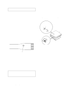
1)
The LINE IN (OPT) jack is used to connect
either a digital (optical) cable or a line
(analog) cable.
2)
The
i
/LINE OUT jack connects either
headphones/earphones or a line cable.
Power requirements
Sony AC Power Adaptor connected at the DC
IN 3V jack:
230–240 V AC, 50/60 Hz (UK and Hong
Kong model)
220–230 V AC, 50/60 Hz (European model)
120 V AC, 50 Hz (Canadian model)
240 V AC, 50 Hz (Australian model)
220 V AC, 50 Hz (Chinese model)
110/220 V AC, 60 Hz (Korean model)
100–240 V AC, 50/60 Hz (Other models)
Nickel metal hydride rechargeable battery NH-
14WM
LR6 (size AA) alkaline battery
Battery operation time
Battery life
1)
When recording
2)
(Unit: approx.hours)(EIAJ
3)
)
1)
The battery life may be shorter due to
operating conditions and the temperature of
the location.
2)
When you record, use a fully charged
rechargeable battery. Recording time may
differ according to the alkaline batteries.
Batteries
Stereo
LP2
LP4
NH-14WM
nickel metal
hydride
rechargeable
battery
4)
8
10.5
13
LR6 (SG)
Sony alkaline
dry battery
5)
7
10
14
NH-14WM
nickel metal
hydride
rechargeable
battery
4)
+ One LR6
(SG)
5)
19
26
30
Frequency response
20 to 20,000 Hz
±
3 dB
120 V AC, 60 Hz (US model)
PORTABLE MINIDISC RECORDER
US Model
Canadian Model
AEP Model
UK Model
E Model
Australian Model
Chinese Model
Tourist Model
SPECIFICATIONS
MZ-R900
US and foreign patents licensed from Dolby
Laboratories Licensing Corporation.
Photo: Red type
– Continued on next page –
Model Name Using Similar Mechanism
NEW
Mechanism Type
MT-MZR900-171
Optical Pick-up Name
LCX-4R
9-927-991-13
Sony Corporation
2001C0500-1
Audio Entertainment Group
C
2001.3
General Engineering Dept.
Ver 1.2
2001. 03