Sony PCV-RZ22G System Reference Manual
Sony PCV-RZ22G - Vaio Desktop Computer Manual
 |
View all Sony PCV-RZ22G manuals
Add to My Manuals
Save this manual to your list of manuals |
Sony PCV-RZ22G manual content summary:
- Sony PCV-RZ22G | System Reference Manual - Page 1
i - Sony PCV-RZ22G | System Reference Manual - Page 2
includes certain software versions or upgrades, and Internet services or offers that are available to U.S. customers only. Sony, VAIO, the VAIO logo, VAIO Smart, Giga Pocket, MovieShaker, DVgate, Handycam, Memory Stick, the Memory Stick logo, Net MD, Network Walkman, OpenMG, MICROMV, SonicStage - Sony PCV-RZ22G | System Reference Manual - Page 3
STAR® Partner, Sony Corporation has determined reduce energy consumption. It is an open system in which business proprietors can participate voluntarily. number and serial number are located on the back panel of your Sony VAIO® computer. Record the model and serial number in the space provided - Sony PCV-RZ22G | System Reference Manual - Page 4
drives may vary, depending on the system configuration you have purchased. See the online specifications sheet for details on your installed optical drives. For questions regarding your product or for the Sony Service Center nearest you, visit the Sony Computing Support Web site at http:// www - Sony PCV-RZ22G | System Reference Manual - Page 5
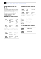
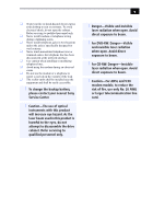
servicing to qualified personnel only. ❑ Never install modem or telephone wiring during a lightning storm. ❑ Never install telephone jacks in wet locations unless the jack is specifically contact your nearest Sony Service Center. ! exposure to beam. ! For CD-RW: Danger-Invisible laser radiation - Sony PCV-RZ22G | System Reference Manual - Page 6
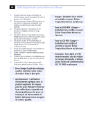
vi VAIO Digital Studio System Reference Manual ❑ pile de rechange, veuillez contacter votre centre de service Sony le plus près. ! Avertissement : L'utilisation d'instruments ouvert. Évitez l'exposition directe au faisceau. ! Pour les CD-RW : Danger- Radiation laser visible et invisible si ouvert. - Sony PCV-RZ22G | System Reference Manual - Page 7
SONY Model No.: PCV-1112 (RZ series model) PCV-7772 (RX series model) Responsible Party: Sony Electronics Inc. Address: 680 Kinderkamack Rd. Oradell, NJ 07649 Telephone: 201-930-6972 This phone number is for FCC-related matters only. This device complies with Part instructions this manual - Sony PCV-RZ22G | System Reference Manual - Page 8
viii VAIO Digital Studio System Reference Manual FCC Part 68 This equipment complies with Part 68 of the FCC rules and the network until the problem is resolved. Repair of this equipment should be made only by a Sony Service Center or Sony authorized agent. For the Sony Service Center nearest you, - Sony PCV-RZ22G | System Reference Manual - Page 9
lithium batteries in household or business trash may be prohibited. For the Sony Service Center nearest you, call 1-888-476-6972 in the United States or by the manufacturer. Discard used batteries according to the manufacturer's instructions. ! The battery pack used in this device may present a - Sony PCV-RZ22G | System Reference Manual - Page 10
x VAIO Digital Studio System Reference Manual Industry Canada Notice This equipment meets the applicable Industry Canada technical specifications. The Ringer Equivalence Number (REN) is an indication of the maximum number of devices allowed to be connected to a telephone interface. The termination - Sony PCV-RZ22G | System Reference Manual - Page 11
vii FCC Part 68 PCV-RZ Series model 2 Drives ...3 Buttons and Switches 4 Indicators 5 Connectors (Models Equipped with Giga Pocket Features)..........6 Rear View (Model Equipped with Giga Pocket Features 7 Icon Labels 8 I/O Connectors 10 Expansion Slots 14 Chapter 2 - Configuring Your System - Sony PCV-RZ22G | System Reference Manual - Page 12
an Open I/O Slot 43 Installing an Additional Hard Disk Drive 44 To identify additional hard disk space 48 Removing the Power Supply (PCV-RX series models 49 Replacing the Power Supply (PCV-RX series model 50 Chapter 4 - System Board 51 Memory Module (DDR-DIMM) Slots 52 Power Supply and - Sony PCV-RZ22G | System Reference Manual - Page 13
Assignments 72 System I/O Address Map 73 Memory Map 75 IRQ Settings 76 Chapter 7 - Specifications 77 Processor ...77 Chipset ...77 AGP Bus...77 PCI Bus ...78 Memory Modules 78 Memory Configurations 78 L2 Cache ...78 Graphics ...78 Audio ...79 Communications 79 Giga Pocket I/O 79 I/O and - Sony PCV-RZ22G | System Reference Manual - Page 14
xiv VAIO Digital Studio System Reference Manual - Sony PCV-RZ22G | System Reference Manual - Page 15
For details on the hardware configuration of your system, see the online specifications sheet. To view this the online specifications sheet: 1 Click Start in the Windows taskbar, then click Help and Support. 2 From the VAIO Help and Support menu, click VAIO User Guide. 3 Locate the link in the text - Sony PCV-RZ22G | System Reference Manual - Page 16
2 VAIO Digital Studio System Reference Manual Front View (PCV-RZ Series model) - Sony PCV-RZ22G | System Reference Manual - Page 17
Components 3 Optical disc drive #1 Optical disc drive #2 Floppy disk drive Memory Stick media slot Drive Optical disc drive #1 Optical disc drive #2 Floppy disk drive Memory Stick® media slot Description See online specifications sheet for details. See online specifications sheet for details - Sony PCV-RZ22G | System Reference Manual - Page 18
4 VAIO Digital Studio System Reference Manual Buttons and Switches Optical disc eject Floppy disk eject Power on/off Button or switch Optical disc eject button Floppy disk eject button Power on/off switch Description Automatically opens and closes the optical drive tray. Ejects a floppy disk. - Sony PCV-RZ22G | System Reference Manual - Page 19
Indicators Identifying Components 5 Floppy disk drive access Power Standby Optical disc drive access Hard disk drive access Indicator Floppy disk drive access indicator Power indicator Standby indicator Optical disc drive access indicator Hard disk drive access indicator Description Light is - Sony PCV-RZ22G | System Reference Manual - Page 20
6 VAIO Digital Studio System Reference Manual Connectors (Models Equipped with Giga Pocket Features) Audio R In jack Audio L In jack Video In jack S-Video In jack i.LINK port USB1, USB2 ports Connector Audio R In jack* Audio L In jack* - Sony PCV-RZ22G | System Reference Manual - Page 21
Identifying Components 7 Rear View (Model Equipped with Giga Pocket Features) AC Input port Mouse port Keyboard port VGA Monitor port i.LINK port USB3, USB4, USB5, USB6 ports Microphone, Headphone, Line In jacks VGA Monitor - Sony PCV-RZ22G | System Reference Manual - Page 22
8 VAIO Digital Studio System Reference Manual Icon Labels Icon Label Area MONITOR USB MIC HEADPHONES LINE IN MONITOR AUDIO S VIDEO/VIDEO AUDIO S VIDEO/VIDEO - VIDEO OUTPUT - - VIDEO1 INPUT - VHF/UHF PHONE - Sony PCV-RZ22G | System Reference Manual - Page 23
Identifying Components 9 Icon Description Microphone jack Headphones jack Line In jack (audio) Audio Out jack Video/S-video Out jack Audio In jack Video/S-video In jack Telephone jack Printer port S/P DIF Optical Out port Ethernet port (for LAN connection only) DVI Monitor port VHF/UHF port - Sony PCV-RZ22G | System Reference Manual - Page 24
10 VAIO Digital Studio System Reference Manual I/O Connectors The following section identifies the various I/O Two USB ports are located at the front, and four at the rear of the system. USB 2.0 technology supports high/full/low-speed USB devices. Ethernet Port The Ethernet port at the rear of the - Sony PCV-RZ22G | System Reference Manual - Page 25
Identifying Components 11 Printer Port The printer port is a standard 25-pin DB-25 female port. 25 13 14 1 VGA Monitor Port The monitor port is a standard 15-pin female high-density VGA-type port located on the AGP plug-in card. 10 15 5 11 1 6 - Sony PCV-RZ22G | System Reference Manual - Page 26
12 VAIO Digital Studio System Reference Manual Microphone, Headphones, and Line In Jacks The microphone, headphones, and Optical Out Port The Plastic Optical Fiber (POF) output port for the Sony®/Phillips Digital Interface (S/P DIF) can be used to connect compatible audio or video equipment, such - Sony PCV-RZ22G | System Reference Manual - Page 27
to 12 V and a maximum power of 6 watts. ✍ i.LINK is a trademark of Sony used only to designate that a product contains an IEEE 1394 connection. The i.LINK connection devices to your system, such as an optical disc or hard disk drive, confirm their operating system compatibility and required - Sony PCV-RZ22G | System Reference Manual - Page 28
System Reference Manual Expansion Slots There are five expansion slots; however, four slot covers are visible from the back panel (see "System Board" on page 51). Expansion Slot No. 5 4 3 2 1 Description Occupied by a VGA and DVI monitor card.* Available for expansion. Occupied by a Giga Pocket - Sony PCV-RZ22G | System Reference Manual - Page 29
Chapter 2 Configuring Your System This chapter contains information on configuring your system. ❑ Making changes to the BIOS settings. ❑ Making changes to the display's power management settings. 15 - Sony PCV-RZ22G | System Reference Manual - Page 30
16 VAIO Digital Studio System Reference Manual Accessing the BIOS Setup Utility Access the BIOS Setup Utility to make changes to the BIOS settings (see "CMOS Setup Options" on page 57 for information on BIOS settings). ! Before rebooting the system, save and close all open files, and exit open - Sony PCV-RZ22G | System Reference Manual - Page 31
Configuring Your System 17 Changing Power Management Settings Power Management capability is designed to enable your computer to reduce power or shut itself off after being idle for a - Sony PCV-RZ22G | System Reference Manual - Page 32
18 VAIO Digital Studio System Reference Manual 2 Select the power scheme that is most appropriate for the way you use your computer. To change a power scheme, change the settings for Turn off monitor, and Turn off hard disks, System stand by, and System hibernates. The Turn off monitor option - Sony PCV-RZ22G | System Reference Manual - Page 33
4 Click the Advanced tab. Configuring Your System 19 5 Select the desired settings. - Sony PCV-RZ22G | System Reference Manual - Page 34
20 VAIO Digital Studio System Reference Manual 6 Click the Hibernate tab. 7 Select the settings most appropriate for your system. - Sony PCV-RZ22G | System Reference Manual - Page 35
you to select and configure an Uninterruptible Power Supply (UPS) device for your system. ✍ A UPS device is an optional accessory not supplied with your system. 9 Select the settings most appropriate for your system and click OK. For more information about configuring a UPS device, refer to the - Sony PCV-RZ22G | System Reference Manual - Page 36
22 VAIO Digital Studio System Reference Manual - Sony PCV-RZ22G | System Reference Manual - Page 37
files, exit all open applications, turn off the power to all attached peripheral devices, shut down the computer, and unplug the power cord. ✍ System configuration may vary, depending on the model purchased. Your computer may not include all of the hardware features shown in the illustrations of - Sony PCV-RZ22G | System Reference Manual - Page 38
VAIO Digital Studio System Reference Manual Removing the Side Panel You must remove the side panel to access the system board, add-on cards, power supply, battery, memory, and internal drives. To remove the side panel (PCV aside. Removing the side panel (PCV-RZ series model equipped with Giga Pocket) - Sony PCV-RZ22G | System Reference Manual - Page 39
Upgrading and Maintaining Components 25 To remove the side panel (PCV-RX series model) 1 Shut down your computer and turn off all peripheral devices, such as your printer. 2 Unplug panel releases. 4 Lift the side panel away from the unit and set aside. Removing the side panel (PCV-RX series model) - Sony PCV-RZ22G | System Reference Manual - Page 40
26 VAIO Digital Studio System Reference Manual Replacing the Side Panel To replace the side panel (PCV-RZ series model) 1 Align tabs on the side panel to the tracks on the chassis frame. 2 Gently slide the side panel onto the chassis, until - Sony PCV-RZ22G | System Reference Manual - Page 41
Upgrading and Maintaining Components 27 To replace the side panel (PCV-RX series model) 1 Align the tabs on the side panel to the chassis rim. 2 Press the side panel firmly against the unit until it snaps into place. Replacing the side panel (PCV-RX series model) - Sony PCV-RZ22G | System Reference Manual - Page 42
28 VAIO Digital Studio System Reference Manual Installing an Add-on Card Your computer may have one or more open expansion slots, depending on the model configuration. An expansion slot enables you to install add-on cards to expand the functionality of your system. The length of the add-on card - Sony PCV-RZ22G | System Reference Manual - Page 43
Upgrading and Maintaining Components 29 ! When removing a slot cover, be careful not to damage components on the system board or add-on cards. You may need to temporarily remove add-on cards or other components that may be next to the slot cover - Sony PCV-RZ22G | System Reference Manual - Page 44
30 VAIO Digital Studio System Reference Manual Installing an add-on card 1 Attach any internal cables that the card requires. See the instructions supplied with the add-on card. 2 Replace the side panel. See "Replacing the Side Panel" on page 26. 3 Reconnect all peripheral devices and the power - Sony PCV-RZ22G | System Reference Manual - Page 45
Upgrading and Maintaining Components 31 Installing an Add-On Card ! Before opening the system unit, save and close all open files, exit all open applications, turn off the power to snugly against the chassis lip after the card is fully inserted. Installing a PCI add-on card (PCV-RX series model) - Sony PCV-RZ22G | System Reference Manual - Page 46
32 VAIO Digital Studio System Reference Manual 5 Replace the screw that secures the card. 6 Attach any necessary cables to the card (see the instructions that came with the add-on card). 7 Replace the side panel (see "Replacing the Side Panel" on page 26). 8 Turn on the computer and follow - Sony PCV-RZ22G | System Reference Manual - Page 47
Components 33 Replacing the Lithium Battery ! Before opening the system unit, save and close all open files, exit all of it in fire. When you remove the lithium battery, all values stored in the CMOS memory (BIOS setup values and Plug and Play values) may be lost. Although the computer can hold - Sony PCV-RZ22G | System Reference Manual - Page 48
VAIO Digital Studio System Reference Manual 8 If necessary, remove any add-on cards to gain access to the battery. You may also need to disconnect some cables. ! Touch any exposed metal part a lithium battery (PCV-RX series model) battery is secure. ✍ The Sony CR2032 battery is recommended. Using - Sony PCV-RZ22G | System Reference Manual - Page 49
Upgrading and Maintaining Components 35 16 If the error message "Error: Check date and time settings." appears during the reboot sequence, press F2 during the reboot process to access the BIOS Setup Utility. If no error message displays, the computer's BIOS settings were retained during the - Sony PCV-RZ22G | System Reference Manual - Page 50
36 VAIO Digital Studio System Reference Manual Removing a Memory Module You may need to remove a memory module if you change the memory configuration or replace a bad module. By default, your computer's memory sockets are filled with DDR-DIMM modules. ! Before opening the system unit, save and close - Sony PCV-RZ22G | System Reference Manual - Page 51
Upgrading and Maintaining Components 37 Removing a memory module (PCV-RZ series model) - Sony PCV-RZ22G | System Reference Manual - Page 52
38 VAIO Digital Studio System Reference Manual Removing a memory module (PCV-RX series model) ✍ The memory modules are located beneath the power supply (applicable to PCV-RX models only). 4 Push down the handle on each side of the memory module to eject the module from its socket. 5 Grasp one edge - Sony PCV-RZ22G | System Reference Manual - Page 53
Side Panel" on page 24). 5 Remove the power supply (see "Removing the Power Supply (PCV-RX series models)" on page 49).* ! Do not remove the Giga Pocket™ card (located in PCI slot No. 3) unless directed by a service technician. The Giga Pocket card is a fragile hardware component. * Applicable to - Sony PCV-RZ22G | System Reference Manual - Page 54
40 VAIO Digital Studio System Reference Manual 6 Align the module over the appropriate socket, noting the location of pin 1 on the module and pin 1 on the socket. Press down here Handles Pin 1 side DDR-DIMM 2 DDR-DIMM 1 Memory module (DDR-DIMM) 1 Indicates pin 1 7 Carefully but firmly insert the - Sony PCV-RZ22G | System Reference Manual - Page 55
handles lock into place. 9 Replace the power supply (see "Replacing the Power Supply (PCV-RX series model)" on page 50).* 10 Replace the side panel (see "Replacing the your computer, the system recognizes the additional memory and automatically make the proper configurations. * Applicable to - Sony PCV-RZ22G | System Reference Manual - Page 56
VAIO Digital Studio System Reference Manual Removing a Slot Cover To install an add-on card that occupies a slot, remove the slot cover. ! Before opening the system 2 Locate the slot whose cover you want to remove. 3 Lay the system on its side. 4 Remove the screw from the slot cover. 5 Remove the - Sony PCV-RZ22G | System Reference Manual - Page 57
computer cannot be properly cooled. This may damage some components, especially the main processor, which generates the most heat. 1 Slide the tip of the slot cover between the chassis and system board. Covering an open I/O slot (PCV-RX series model) 2 Push the slot cover down until it rests firmly - Sony PCV-RZ22G | System Reference Manual - Page 58
VAIO Digital Studio System Reference Manual Installing an Additional Hard Disk Drive Your computer is equipped with an available bay to accommodate an additional 3.5-inch hard disk drive. The hard disk new drive's documentation for configuration instructions). Power connector Jumpers Drive connector 2 Remove - Sony PCV-RZ22G | System Reference Manual - Page 59
Upgrading and Maintaining Components 45 3 Disconnect the drive connector (A). Disconnecting the system (PCV-RX series model) A B C Drive connector Power supply connector Tab Disk drive holder 4 Disconnect the power connector (B). 5 Pull out on the tab (C) that secures the drive holder to the - Sony PCV-RZ22G | System Reference Manual - Page 60
46 VAIO Digital Studio System Reference Manual 6 Slide the drive holder up and out. Installing an internal hard disk drive (PCV-RX series model) 7 Slide the new drive into the bottom part of the drive holder and align the holes on each side of the drive holder. 8 Secure the drive to the drive holder - Sony PCV-RZ22G | System Reference Manual - Page 61
latch the holder to the chassis. Installing an internal hard disk drive (PCV-RX series model) C E B D A Drive connectors Power connectors Tab Disk drive holder 11 Connect the inner drive cable connector (B) to on page 26). 16 Reconnect the power cord to the system and then turn on your computer. - Sony PCV-RZ22G | System Reference Manual - Page 62
48 VAIO Digital Studio System Reference Manual To identify additional hard disk space When you initialize the new hard disk drive, it must be configured as an extended partition in Windows NT file system (NTFS) format. 1 Log on in Windows® as Administrator. 2 Click Start in the Windows taskbar and - Sony PCV-RZ22G | System Reference Manual - Page 63
Upgrading and Maintaining Components 49 Removing the Power Supply (PCV-RX series models) Remove the power supply when you insert a memory module (see "Removing a Memory Module" on page 36). ! Before opening the system unit, save and close all open files, exit all open applications, turn off the - Sony PCV-RZ22G | System Reference Manual - Page 64
50 VAIO Digital Studio System Reference Manual Replacing the Power Supply (PCV-RX series model) 1 Rotate the power supply down and slide it down along the rails on each side of the chassis opening. 2 Replace the screw that secures the power supply to the rear of the chassis. - Sony PCV-RZ22G | System Reference Manual - Page 65
This chapter identifies and describes components on the system board. i.LINK Header (to front panel) Memory Processor CPU Fan Keyboard, Mouse Printer, Monitor, i.LINK USB3, USB4, S/P DIF Out USB5, USB6, Ethernet Mic In, Line In, Line Out CD-In Aux-In Slot No. 1 (CNR)* Slot No. 2 (PCI - Sony PCV-RZ22G | System Reference Manual - Page 66
DDR-DIMM1 DDR-DIMM2 52 VAIO Digital Studio System Reference Manual Memory Module (DDR-DIMM) Slots Memory module (DDR-DIMM) 1 Indicates pin 1 Align pin 1 of the Dual Inline Memory Module (DDR-DIMM) to the small triangle located on the memory module slot of the system board. - Sony PCV-RZ22G | System Reference Manual - Page 67
Board 53 Power Supply and Aux Power Headers The power supply header on the system board connects to the power supply header labelled P1. 2 4 1 3 10 20 1 11 Power Supply header Pin Signal Name 1 +3.3 V 2 +3.3 V 3 Ground 4 +5 V 5 Ground 6 +5 V 7 Ground 8 PWRGD (Power Good - Sony PCV-RZ22G | System Reference Manual - Page 68
54 VAIO Digital Studio System Reference Manual Power Supply header (Continued) Pin Signal Name 16 Ground 17 Ground 18 No Connection 19 +5 V 20 +5 V Aux Power header Pin Signal Name 1 Ground 2 Ground 3 +12 V 4 +12 V - Sony PCV-RZ22G | System Reference Manual - Page 69
123 CLR CMOS Jumper Settings Jumper Plug Position 1-2 2-3 Function Clear CMOS Password Normal ✍ The configuration jumpers should never need changing unless otherwise directed by a technical support or service technician. - Sony PCV-RZ22G | System Reference Manual - Page 70
56 VAIO Digital Studio System Reference Manual - Sony PCV-RZ22G | System Reference Manual - Page 71
option. The option shown in [brackets] on the screen is the option currently set for your system. The other available options for each item are shown without brackets directly below the default option in this guide. The available options are listed in the order they occur when you press the + key - Sony PCV-RZ22G | System Reference Manual - Page 72
58 VAIO Digital Studio System Reference Manual Press F10 to save the changes and exit, or press Esc to discard the changes. Follow the on-screen prompts for other choices. The bottom of the screen presents a summary of the keys to use for navigation and control. - Sony PCV-RZ22G | System Reference Manual - Page 73
User Password Installed Memory BIOS Revision/Version CMOS Setup Options 59 [00:00:00] [01/01/2003] (see "IDE Sub-Menus" on page 60) (see "IDE Sub-Menus" on page 60) (see "IDE Sub-Menus" on page 60) (see "IDE Sub-Menus" on page 60) [Disabled] [Disabled] See online specifications sheet for - Sony PCV-RZ22G | System Reference Manual - Page 74
60 VAIO Digital Studio System Reference Manual IDE Sub-Menus Type Translation Method* Cylinders† Heads† Sectors‡ CHS Capacity* Maximum LBA Capacity* Multi-Sector Transfers* PIO Mode** ULTRA DMA Mode† Set Device As†† [Auto] User Type HDD CD-ROM LS-120 ZIP-100 MO Other ATAPI None [LBA] Large Normal - Sony PCV-RZ22G | System Reference Manual - Page 75
CMOS Setup Options 61 Advanced Screen CPU Speed [1500MHz]* Hyper Threading Technology [Enabled]† Disabled I/O Device Configuration (see "I/O Device Configuration Sub-Menu" on page 62) PCI Configuration (see "PCI Configuration Sub-Menu" on page 62) * CPU Speed may vary, depending on the - Sony PCV-RZ22G | System Reference Manual - Page 76
62 VAIO Digital Studio System Reference Manual I/O Device Configuration Sub-Menu Onboard AC97 Audio Controller Onboard AC97 Modem Controller Onboard 1394 Controller Onboard Lan Controller Onboard Parallel Port Parallel Port Mode Onboard Memory Stick Controller PCI Configuration Sub-Menu Slot 1 IRQ - Sony PCV-RZ22G | System Reference Manual - Page 77
Power Screen Power Up Control AC PWR Loss Restart Wake On LAN Hardware Monitor MB Temperature CPU Temperature CPU Fan Speed Power Fan Speed VCORE Voltage +3.3V Voltage +5V Voltage +12V Voltage CMOS Setup Options 63 [Disabled] Enabled [Disabled] Enabled [(displays actual temperature)] Ignore [( - Sony PCV-RZ22G | System Reference Manual - Page 78
64 VAIO Digital Studio System Reference Manual Boot Screen 1. ATAPI CD-ROM 2. Removable Device 3. IDE Hard Drive 4. Other Boot Device Silent Boot [(displays installed drive)] Disabled [Legacy Floppy] LS120 ZIP-100 ATAPI MO USB FDD Disabled [( - Sony PCV-RZ22G | System Reference Manual - Page 79
Exit Screen Exit Saving Changes Exit Discarding Changes Load Setup Defaults Discard Changes Save Changes CMOS Setup Options 65 - Sony PCV-RZ22G | System Reference Manual - Page 80
66 VAIO Digital Studio System Reference Manual - Sony PCV-RZ22G | System Reference Manual - Page 81
: ❑ User and Supervisor password ❑ Beep code error messages ❑ PCI configuration status and error messages ❑ DMA channel assignments ❑ System I/O address map ❑ Memory map ❑ IRQ settings ✍ Models equipped with Giga Pocket features may require increased system resources due to additional hardware. 67 - Sony PCV-RZ22G | System Reference Manual - Page 82
68 VAIO Digital Studio System Reference Manual User and Supervisor Passwords The system allows you to specify up to two passwords (a User password and a Supervisor password) in the CMOS Setup Utility. The User password is required; the Supervisor - Sony PCV-RZ22G | System Reference Manual - Page 83
69 Beep Code Error Messages During a normal bootup, a single short beep signifies that the system is OK. Other beep patterns signify errors. The number of beeps indicates the specific error that occurred. If a system error occurs, the Sony Online Support technicians require the number of beeps your - Sony PCV-RZ22G | System Reference Manual - Page 84
VAIO Digital Studio System Reference Manual PCI Configuration Status and Error Messages The following is a list of status and error messages that may appear on your system from time to time. Message Floppy Disk primary boot device (hard disk drive, floppy disk drive, CD-ROM drive, or network - Sony PCV-RZ22G | System Reference Manual - Page 85
Miscellaneous Technical Information 71 Message Secondary IDE Controller Resource Conflict Static Device Resource Conflict System Board Device Resource Conflict Meaning The secondary IDE controller has requested a resource that is already in use. A non-Plug and Play ISA card has requested a - Sony PCV-RZ22G | System Reference Manual - Page 86
72 VAIO Digital Studio System Reference Manual DMA Channel Assignments This shows the factory default values. The Windows® operating system reassigns resources to best meet the needs of a particular configuration. DMA Channel Channel 4 Channel 2 Default Assignment Direct memory access controller - Sony PCV-RZ22G | System Reference Manual - Page 87
GeForce™ FX 5800 Ultra SiS Accelerated Graphics Port NVIDIA GeForce FX 5800 Ultra (Sony) ISAPNP Read Data Port ISAPNP Read Data Port ISAPNP Read Data Port Motherboard controller Direct memory access controller Direct memory access controller Direct memory access controller System timer System CMOS/ - Sony PCV-RZ22G | System Reference Manual - Page 88
Status Numeric data processor Standard floppy disk controller Standard floppy disk controller Printer Port (LPT1) Standard 101/102-Key or Microsoft® Natural PS/2® Keyboard Standard 101/102-Key or Microsoft Natural PS/2 Keyboard Motherboard resources Motherboard resources Sony Memory Stick controller - Sony PCV-RZ22G | System Reference Manual - Page 89
Miscellaneous Technical Information 75 Memory Map Resource 0x0000-0x9FFFF 0xF0000-0xFFFFF 0x100000-0x1FFFFFFF 0xFEC00000-0xFECFFFFF 0xE3800FFF Device System board System board System board System board System board PCI bus SiS® Accelerated Graphics Port NVIDIA® GeForce™ FX 5800 Ultra (Sony) PCI - Sony PCV-RZ22G | System Reference Manual - Page 90
76 VAIO Digital Studio System Reference Manual IRQ Settings Resource 0 1 6 8 11 12 13 14 15 16 17 18 18 18 18 20 20 21 22 23 Device System timer Standard 101/102-Key or Microsoft® Natural PS/2® Keyboard Standard floppy disk controller System CMOS/real time clock Sony Memory Stick controller (WB) - Sony PCV-RZ22G | System Reference Manual - Page 91
describes the technical specifications for your VAIO Digital Studio™ computer. ✍ System configuration may vary, depending on the model purchased. Your computer may not include all of the hardware features discussed in this section. Processor See online specifications sheet for details. Chipset - Sony PCV-RZ22G | System Reference Manual - Page 92
78 VAIO Digital Studio System Reference Manual PCI Bus PCI Level 2.2, 33 MHz zero wait state Three PCI slots - not all slots are available. (See online specifications sheet for details.) Memory Modules Installed memory Maximum memory Voltage Pins Memory type See online specifications sheet for - Sony PCV-RZ22G | System Reference Manual - Page 93
modem may vary, depending on the system configuration purchased. † This modem is capable of downloading at 56 Kbps. Your phone service, online service, or Internet Service Provider may not support this technology or operate at this speed. Giga Pocket I/O* Rear Front Audio L/R In jack Video - Sony PCV-RZ22G | System Reference Manual - Page 94
(supports up to 2.88 MB) 3.5-inch, 1.44 MB. Hard Drives and Controller Drive EIDE controller IDE hard drive* Description Supports up to four EIDE drives (supports PIO Mode 4 EIDE drives and Ultra DMA/100 Mode drives) See online specifications sheet for details. * Bus-mastering EIDE driver - Sony PCV-RZ22G | System Reference Manual - Page 95
sheet for details. See online specifications sheet for details. System BIOS Make and model ROM Passwords Power management Advanced features Plug and Play devices Special features Award-based 2 Mb Flash-ROM User and supervisor passwords supported APM 1.2 ACPI-1.0 compliant hardware for use with - Sony PCV-RZ22G | System Reference Manual - Page 96
82 VAIO Digital Studio System Reference Manual - Sony PCV-RZ22G | System Reference Manual - Page 97
69 PCI configuration 70 expansion slots 14 specifications for 80 expansion slots - See slots F fax/modem - See modem card floppy disk drive specifications 80 front view 2 buttons and switches 4 connectors 5, 6 indicators 5 G Giga Pocket specifications 79 graphics controller - See graphics graphics - Sony PCV-RZ22G | System Reference Manual - Page 98
1 Optical drive performance of discs 3, 81 P panel 26 removing 24 passwords, user and supervisor 68 PCI add-on card installing 31 PCI bus specifications 78 power connector 53 power management, configuring 17 processor specifications 77, 78 R RAM - See system memory rear view 7 I/O connectors 10 - Sony PCV-RZ22G | System Reference Manual - Page 99
, removing 42 specifications AGP bus 77 audio 79 BIOS 81 chipset 77 communications 79 floppy disk drive and controller 80 Giga Pocket 79 graphics 78 hard drives and controllers 80 I/O and expansion slots 80 L2 cache 78 memory configurations 78 memory module 78 PCI bus 78 processor 77, 78 status - Sony PCV-RZ22G | System Reference Manual - Page 100
86 VAIO Digital Studio System Reference Manual
-
 1
1 -
 2
2 -
 3
3 -
 4
4 -
 5
5 -
 6
6 -
 7
7 -
8
-
9
-
10
-
11
-
12
-
13
-
14
-
15
-
16
-
17
-
18
-
19
-
20
-
21
-
22
-
23
-
24
-
25
-
26
-
27
-
28
-
29
-
30
-
31
-
32
-
33
-
34
-
35
-
36
-
37
-
38
-
39
-
40
-
41
-
42
-
43
-
44
-
45
-
46
-
47
-
48
-
49
-
50
-
51
-
52
-
53
-
54
-
55
-
56
-
57
-
58
-
59
-
60
-
61
-
62
-
63
-
64
-
65
-
66
-
67
-
68
-
69
-
70
-
71
-
72
-
73
-
74
-
75
-
76
-
77
-
78
-
79
-
80
-
81
-
82
-
83
-
84
-
85
-
86
-
87
-
88
-
89
-
90
-
91
-
92
-
93
-
94
-
95
-
96
-
97
-
98
-
99
-
100
 |
 |