Sony STR-K740P Operating Instructions (primary manual)
Sony STR-K740P - Fm Stereo/fm-am Receiver Manual
 |
View all Sony STR-K740P manuals
Add to My Manuals
Save this manual to your list of manuals |
Sony STR-K740P manual content summary:
- Sony STR-K740P | Operating Instructions (primary manual) - Page 1
377-12(2) FM Stereo FM-AM Receiver Operating Instructions GB Owner's Record The model and serial numbers are located on the rear panel. Record the serial number in the space provided below. Refer to them whenever you call upon your Sony dealer regarding this product. Model No. HT-DDW840/DDW740 - Sony STR-K740P | Operating Instructions (primary manual) - Page 2
the user to the presence of important operating and maintenance (servicing) instructions in Sony Corporation has determined that this product meets the ENERGY STAR® guidelines for energy efficiency. This receiver incorporates Dolby* Digital and Pro Logic Surround and the DTS** Digital Surround System - Sony STR-K740P | Operating Instructions (primary manual) - Page 3
hookups 8 Video component hookups 9 Digital component hookups 10 Multi channel input hookups1 11 Other hookups 12 Hooking Up and Setting Up the Speaker System Speaker system hookups 13 Performing initial setup operations ..... 15 Multi channel surround setup 15 Checking the connections 21 - Sony STR-K740P | Operating Instructions (primary manual) - Page 4
- Receiver - Speaker system • Front/surround speakers • Center speaker • Sub woofer STR-K840P SS-MSP2 SS-CNP2 SA-WMSP4 The HT-DDW740 consists of: - Receiver - Speaker system • Front/surround speakers • Center speaker • Sub woofer STR-K740P SS-MSP2 SS-CNP2 SA-WMSP2 About area codes The area code - Sony STR-K740P | Operating Instructions (primary manual) - Page 5
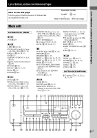
9 (25) Digital Cinema Sound (indicator) qs (24) DIMMER ej (23) DISPLAY 2 (23, 34, 52) Display qa (23) DVD/LD wa (22) E - L ENTER wl (36) FM (Except for models of area code CEL, CEK) ed (31, 32) FM/AM (Models of area code CEL, CEK only) es (31, 32) 1 23 4 FM MODE (Models of area code CEL, CEK only - Sony STR-K740P | Operating Instructions (primary manual) - Page 6
to avoid hum and noise. • When connecting an audio/video cord, be sure to match the color-coded pins to the appropriate jacks on the components: yellow (video) to yellow; white (left, audio) to white; and red (right, audio) to red. • When you connect optical digital cords, insert the cord plugs - Sony STR-K740P | Operating Instructions (primary manual) - Page 7
FM wire antenna* (supplied) DIGITAL OPTICAL VIDEO 2 IN ANTENNA AM MONITOR DVD/LD IN COAXIAL FM 75Ω COAXIAL VIDEO IN VIDEO IN VIDEO OUT VIDEO IN VIDEO OUT L CENTER R SUB FRONT SURROUND WOOFER MULTI CH IN AUDIO OUT L R IN CD OUT IN AUDIO IN AUDIO IN AUDIO OUT AUDIO IN SUB MD/TAPE DVD/LD - Sony STR-K740P | Operating Instructions (primary manual) - Page 8
DIGITAL OPTICAL VIDEO 2 IN MD or Tape deck INPUT OUTPUT LINE LINE L R A A ç ç OUT IN ANTENNA AM MONITOR DVD/LD IN COAXIAL FM 75Ω COAXIAL VIDEO IN VIDEO IN VIDEO OUT VIDEO IN VIDEO OUT L CENTER R SUB FRONT SURROUND WOOFER MULTI CH IN AUDIO OUT L R IN CD OUT IN AUDIO IN AUDIO - Sony STR-K740P | Operating Instructions (primary manual) - Page 9
VIDEO OUT B DIGITAL OPTICAL VIDEO 2 IN ANTENNA AM MONITOR DVD/LD IN COAXIAL FM 75Ω COAXIAL VIDEO IN VIDEO IN VIDEO OUT VIDEO IN VIDEO OUT L CENTER R SUB FRONT SURROUND WOOFER MULTI CH IN AUDIO OUT L R IN CD OUT IN AUDIO IN AUDIO IN AUDIO OUT AUDIO IN SUB MD/TAPE DVD/LD VIDEO 2 VIDEO - Sony STR-K740P | Operating Instructions (primary manual) - Page 10
.) to the receiver's digital input jacks to bring the multi channel surround sound of a movie theater into your home. To fully enjoy multi channel surround sound, five speakers (two front speakers, two surround speakers, and a center speaker) and a sub woofer are required. You can also connect an LD - Sony STR-K740P | Operating Instructions (primary manual) - Page 11
13 for details on speaker system hookup. DIGITAL OPTICAL VIDEO 2 IN ANTENNA AM MONITOR DVD/LD IN COAXIAL FM 75Ω COAXIAL VIDEO IN VIDEO IN VIDEO OUT VIDEO IN VIDEO OUT L CENTER R SUB FRONT SURROUND WOOFER MULTI CH IN AUDIO OUT L R IN CD OUT IN AUDIO IN AUDIO IN AUDIO OUT AUDIO IN SUB MD - Sony STR-K740P | Operating Instructions (primary manual) - Page 12
120V 240V 220V AC power cord b To a wall outlet Connecting the AC power cord Before connecting the AC power cord of this receiver to a wall outlet, connect the speaker system to the receiver (page 13). Connect the AC power cord(s) of your audio/ video components to a wall outlet. 12GB - Sony STR-K740P | Operating Instructions (primary manual) - Page 13
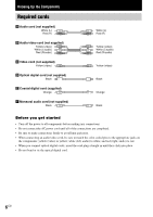
system hookups Required cords A Speaker cords (supplied) (+) (-) B Monaural audio cord (supplied) Black (+) (-) Black Active sub woofer INPUT AUDIO IN B E Front speaker (R) A Ee Front speaker (L) A MONITOR VIDEO OUT AUDIO OUT SUB WOOFER SPEAKERS IMPEDANCE USE 8 - 16Ω SURROUND R L CENTER - Sony STR-K740P | Operating Instructions (primary manual) - Page 14
of poor conditions of the speaker cord Stripped speaker cord is touching another speaker terminal. Notes • Connect the long speaker connecting cords to the surround speaker terminals and the short speaker connecting cords to the front and center speaker terminals. • Twist the stripped ends - Sony STR-K740P | Operating Instructions (primary manual) - Page 15
for other settings. Multi channel surround setup For the best possible surround sound, all speakers should be the same distance from the listening position (A). However, the receiver lets you place the center speaker up to 1.5 meters (5 feet) closer (B) and the surround speakers up to 4.5 meters - Sony STR-K740P | Operating Instructions (primary manual) - Page 16
Speaker) according to the supplied speaker system. When you select MICRO SP., the speaker size and sub woofer selection has been configurated as follows: Speaker FRONT CENTER SURROUND Initial setting 5.0 m (16 ft.)* 5.0 m (16 ft.)* 3.5 m (11 ft.)* BEHD. LOW * Models of area code U, CA only. 16GB - Sony STR-K740P | Operating Instructions (primary manual) - Page 17
The receiver allows you to input the speaker position in terms of distance. However, it is not possible to set the center speaker further than the front speakers. Also, the center speaker cannot be set more than 1.5 meters (5 feet) closer than the front speakers. Likewise, the surround speakers can - Sony STR-K740P | Operating Instructions (primary manual) - Page 18
set to "NO". Tip The surround speaker position parameter is designed specifically for implementation of the Digital Cinema Sound modes with virtual elements. With the Digital Cinema Sound modes, speaker position is not as critical as other modes. All modes with virtual elements were designed under - Sony STR-K740P | Operating Instructions (primary manual) - Page 19
the bass redirection circuitry and output the surround channel bass frequencies from the sub woofer or other "LARGE" speakers. • If you do not connect surround speakers, select "NO".*3 Tip *1-*3 correspond to the following Dolby Pro Logic modes *1 NORMAL *2 PHANTOM *3 3 STEREO Tip Internally, the - Sony STR-K740P | Operating Instructions (primary manual) - Page 20
Multi channel surround setup (continued) Adjusting the speaker level Use the remote while seated in your listening position to adjust the level of each speaker. Note The receiver incorporates a new test tone with a frequency centered at 800 Hz for easier speaker level adjustment. 1 Press ?/1 to turn - Sony STR-K740P | Operating Instructions (primary manual) - Page 21
Up and Setting Up the Speaker System Checking the connections After connecting all of your components to the receiver, do the following to verify that the connections were made correctly. 1 Press ?/1 to turn on the receiver. 2 Turn on the component that you connected (e.g., CD player or tape deck - Sony STR-K740P | Operating Instructions (primary manual) - Page 22
(HT-DDW840 only) Press MULTI CH IN to enjoy the audio source connected to the MULTI CH IN jacks. You can adjust balance and level of all the speakers. When this function is on, the tone and surround effects are turned off. MULTI CHANNEL DECODING indicator (HT-DDW840 only) This indicator lights up - Sony STR-K740P | Operating Instructions (primary manual) - Page 23
Basic Operations Changing the display DISPLAY Each time you press DISPLAY, the display spaces have been entered, or it is the same as the function. ** During RDS reception only. (Models of area code CEL, CEK only. See page 34). DIMMER Press DIMMER repeatedly to adjust the brightness of the display - Sony STR-K740P | Operating Instructions (primary manual) - Page 24
15 to set the speaker parameters before enjoying surround sound. Automatically decoding the input audio signal Press A.DEC. "AUTO DEC." appears in the display. This mode automatically detects the type of audio signal being input (Dolby Digital, DTS, or standard 2 channel stereo) and performs the - Sony STR-K740P | Operating Instructions (primary manual) - Page 25
any sound coming directly from the surround speakers. Selecting other sound fields Press MODE repeatedly to select the sound field you want. The current sound field is indicated in the display. x NORM.SURR. (Normal Surround) Software with multi channel surround audio signals is played back according - Sony STR-K740P | Operating Instructions (primary manual) - Page 26
. Dolby Digital discs are labeled with the logo, and Dolby Surround encoded programs mode outputs the sound from the front left and right speakers only. Standard 2 channel (stereo) sources completely bypass the sound field processing. Multi channel surround formats are downmixed to 2 channel - Sony STR-K740P | Operating Instructions (primary manual) - Page 27
signals recorded in the Dolby Digital format. 2 PRO LOGIC: Lights up when the receiver applies Pro Logic processing to 2 channel signals in order to output the center and surround channel signals. However, this indicator does not light if the center and surround speakers are set to "NO", and - Sony STR-K740P | Operating Instructions (primary manual) - Page 28
to the parameters. See the tables on 58 for the parameters available in each sound field. To get the most from multi channel surround sound Position your speakers and do the procedures described in "Multi channel surround setup" starting from page 15 before you customize a sound field. Adjusting the - Sony STR-K740P | Operating Instructions (primary manual) - Page 29
speakers. Center level (CTR XXX dB) Lets you adjust the level of the center speaker. Surround left level (SUR.L. XXX dB) Lets you adjust the level of the surround left speaker. Surround sub woofer from the front, center or surround channels via the Dolby Digital or DTS bass redirection circuitry. - Sony STR-K740P | Operating Instructions (primary manual) - Page 30
TREBLE +/- button lets you adjust the tone (bass or treble) of the front speakers for optimum sound. You can adjust the tone for each separate sound field. 1 Start playing a program source encoded with multi channel surround sound. 2 Press BASS +/- or TREBLE +/- to adjust the tone. The setting is - Sony STR-K740P | Operating Instructions (primary manual) - Page 31
Receiving Broadcasts Receiving Broadcasts Before receiving broadcasts, make sure you have connected FM and AM antennas to the receiver (page 7). Storing FM stations automatically (AUTOBETICAL) (Models of area code CEL, CEK only) This function lets you store up to 30 FM and FM RDS stations in - Sony STR-K740P | Operating Instructions (primary manual) - Page 32
press FM MODE to change models of area code CEL, CEK: FM/AM. Preset tuning After you have tuned in stations using Direct Tuning or Automatic Tuning, you can preset them to the receiver. Then you can tune in any of the stations directly by entering its 2-character preset code using the supplied remote - Sony STR-K740P | Operating Instructions (primary manual) - Page 33
and direction as follows: nA1˜A2˜...˜A0˜B1˜B2˜...˜B0N nC0˜...C2˜C1N * For models of area code CEL, CEK: PRESET/PTY SELECT + or PRESET/PTY SELECT -. Using the preset codes Use the supplied remote to perform the following operations. For details on the buttons used in this section, see pages 39-45 for - Sony STR-K740P | Operating Instructions (primary manual) - Page 34
Using the Radio Data System (RDS) (Models of area code CEL, CEK only) This receiver also allows you to use RDS (Radio Data System), which enables radio stations to send additional information along with the regular program signal. You can use the following convenient RDS features: - Displaying RDS - Sony STR-K740P | Operating Instructions (primary manual) - Page 35
Receiving Broadcasts Description of program types Program type indication NEWS AFFAIRS INFO SPORT programs Country music programs Programs featuring the popular music of the country or region Programs featuring oldies music Folk music programs Investigative features Any programs not defined above - Sony STR-K740P | Operating Instructions (primary manual) - Page 36
(Models of area code CEL, CEK only) You cannot change the name of an RDS station. Recording Before you begin, make sure you've connected all components properly. Recording on an audio tape or MiniDisc You can record on a cassette tape or MiniDisc using the receiver. See the operating instructions - Sony STR-K740P | Operating Instructions (primary manual) - Page 37
connections to the VIDEO 2 and DVD/LD inputs. Analog recording is not possible if you make only digital connections. • When MULTI CH IN is selected, the analog audio signals of the current function is output from the REC OUT jacks (HT-DDW840 ony). Using the Sleep Timer You can set the receiver - Sony STR-K740P | Operating Instructions (primary manual) - Page 38
is ideal for the movies encoded in Dolby Surround. Besides, this mode can reproduce the sound in 5.1 channel when watching the videos of old movies or in the dubbed language. • When set to "II MUSIC", the receiver performs the Pro Logic II music mode decoding. This setting is ideal for the normal - Sony STR-K740P | Operating Instructions (primary manual) - Page 39
MODE N X x TOP MENU/ GUIDE MUTING AV MENU F MASTER VOL G g f O DISPLAY TV VOL RETURN/EXIT TV/ MAIN TV CH VIDEO MENU WIDE ON SCREEN The tables below show the settings of each button. Remote Button ?/1 SLEEP VIDEO 1 VIDEO 2 Operations Function Receiver Receiver Receiver Receiver - Sony STR-K740P | Operating Instructions (primary manual) - Page 40
mode. Select Dual Mono or Bilingual sound of Dolby Digital, DTS or AAC, etc. Selects 2CH ANALOG DIRECT. Selects 2CH mode. Selects sound field mode / DAT deck SYSTEM Receiver/TV/ Turns off the receiver and STANDBY VCR/Satellite other Sony audio/video (Press tuner/CD components. AV ?/1 player/VCD - Sony STR-K740P | Operating Instructions (primary manual) - Page 41
Remote RM-PP411 Remote Operations Function Button AUDIO TV/ VCR/ Changes the sound to DVD player Multiplex, Bilingual or Multi channel DAT deck/ Tape deck Skips tracks. * Only for Sony TVs with the picture-in-picture function. Remote Operations Button m/M CD player/ VCD player/ DVD player/ LD - Sony STR-K740P | Operating Instructions (primary manual) - Page 42
remote. AV1 and Remote AV2 Select the command mode of the remote. SOURCE Remote Selects 2ND AV output. ALT Remote Change remote key function to activate those buttons with orange printing. Notes • Some functions explained in this section may not work depending on the model of the receiver - Sony STR-K740P | Operating Instructions (primary manual) - Page 43
. Furthermore, you can also program the remote for Sony components that the remote is unable to control. Note that the remote can only control components that accept infrared wireless control signals. 1 Press AV ?/1 while pressing down USE MODE. The indicator lights. 2 Press the function button - Sony STR-K740P | Operating Instructions (primary manual) - Page 44
and the maker of the component Use the numeric codes in the tables below to control non-Sony components and also Sony components that the remote is normally unable to control. Since the remote signal that a component accepts differs depending on the model and year of the component, more than one - Sony STR-K740P | Operating Instructions (primary manual) - Page 45
Operations Using the Remote RM-PP411 To control a VCR Maker SONY AIWA AKAI BLAUPUNKT EMERSON FISHER GENERAL ELECTRIC GOLDSTAR GRUNDIG HITACHI ITT/NOKIA JVC MAGNAVOX MITSUBISHI/MGA NEC PANASONIC PHILIPS PIONEER RCA/PROSCAN SAMSUNG SANYO SHARP TELEFUNKEN TOSHIBA ZENITH Code(s) 701, 702, 703, 704, - Sony STR-K740P | Operating Instructions (primary manual) - Page 46
button description AV SLEEP ?/1 ?/1 SYSTEM STANDBY VIDEO 1 VIDEO 2 DVD/LD MD/TAPE CD TUNER TOP MENU 1 DVD MENU F 23 G 4 7 ENTER g 56 f O 89 SHIFT >10 0 - - CH/PRESET + .> m M D.TUNING ENTER RETURN TV/VIDEO ANT TV/VTR D.SKIP N X x SOUND FIELD A.DEC MODE 2CH TEST TONE - Sony STR-K740P | Operating Instructions (primary manual) - Page 47
/ LD player/ DVD player/ MD deck/ DAT deck Turns the audio and video components on or off. SYSTEM STANDBY (Press AV ?/1 and ?/1 at the same time) Receiver/TV/ Turns off the receiver and VCR/Satellite other Sony audio/video tuner/CD components. player/VCD player/LD player/ DVD player/MD - Sony STR-K740P | Operating Instructions (primary manual) - Page 48
of the TV might not switch to the corresponding input mode that you want. In this case, press the TV/VIDEO button to switch the input mode of the TV. • Some functions explained in this section may not work depending on the model of the receiver. • The above explanation is intended to serve as an - Sony STR-K740P | Operating Instructions (primary manual) - Page 49
VTR 2*) VCR (command mode VTR 3*) TV DSS (Digital Satellite Receiver) DVD VCD player Press 1 2 3 4 5 6 7 8 9 0 >10 ENTER . * Sony VCRs are operated with a VTR 1, 2 or 3 setting. These correspond to Beta, 8mm and VHS respectively. Now you can use the MD/TAPE button to control the tape deck. To - Sony STR-K740P | Operating Instructions (primary manual) - Page 50
of the following difficulties while using the receiver, use this troubleshooting guide to help you remedy the problem. Also, see "Checking the connections" on page 21 to verify that the connections are correct. Should any problem persist, consult your nearest Sony dealer. There is no sound or only - Sony STR-K740P | Operating Instructions (primary manual) - Page 51
's optical or coaxial digital output to the receiver's jack. When making this connection, be sure to set INPUT MODE manually (page 22). The receiver may not operate correctly if INPUT MODE is set to "AUTO IN". For details on DOLBY DIGITAL RF hookups, see the operating instructions supplied - Sony STR-K740P | Operating Instructions (primary manual) - Page 52
an unclear picture appears on the TV screen or monitor. • Select the appropriate function on the receiver. • Set your TV to the appropriate input mode. • Move your TV away from the audio components. The remote does not function. • The VIDEO3, TV/SAT, PHONO, AUX, SOURCE, MPX/DUAL, ANALOG DIRECT, 12 - Sony STR-K740P | Operating Instructions (primary manual) - Page 53
K840P only)/80 watts (STR-K740P only) per channel minimum RMS power, with no more than 0.09 % total harmonic distortion from 250 milliwatts to rated output (Models of area code U only). Amplifier section POWER OUTPUT Models of area code U, CA Rated Power Output at Stereo Mode (8 ohms 40 Hz - 20 - Sony STR-K740P | Operating Instructions (primary manual) - Page 54
Specifications (continued) Inputs (Digital) DVD/LD (Coaxial) VIDEO 2 (Optical) Sensitivity: - Impedance: 75 ohms S/N: 100 dB (A, 20 kHz LPF) Sensitivity: - Impedance: - S/N: 100 dB (A, 20 kHz LPF) Outputs MD/TAPE (OUT), VIDEO 1 (AUDIO OUT) SUB WOOFER Voltage: 250 mV Impedance: 10 kilohms Voltage - Sony STR-K740P | Operating Instructions (primary manual) - Page 55
STR-K740P: 155 W Power consumption (during standby mode) 0.5 W Dimensions 430 × 145 × 298 mm (16 7/8 × 5 6/8 × 11 6/8 inches) including projecting parts and controls Mass (Approx.) 7.0 kg (15 lb 7 oz) Speaker section SS-MSP2 for front and surround speakers SS-CNP2 for center speaker Speaker - Sony STR-K740P | Operating Instructions (primary manual) - Page 56
connecting cord (1 phono to 1 phono) (1) Coaxial digital cord (1) Foot pads (speakers) (20) Foot pads (subwoofer) (4) Remote commander (1) • RM-PP411 (HT-DDW840 only) • RM-U306 (HT-DDW740 only) R6 (size -AA) batteries (2) Speakers • Front speakers (2) • Surround speakers (2) • Center speaker - Sony STR-K740P | Operating Instructions (primary manual) - Page 57
R (FRONT)1) LARGE, SMALL C (CENTER)1) LARGE, SMALL, NO SL SR (SURROUND)1) LARGE, SMALL, NO SW (SUB MODE.AVX AV1, AV2 PRO LOGIC 5) DOLBY PL, MOVIE, MUSIC 1) Only when you select NORM. SP. 2) For models of area code U, CA: between 3 feet and 40 feet (1 foot steps) 3) For models of area code - Sony STR-K740P | Operating Instructions (primary manual) - Page 58
z z z z z z z z z z z CENTER SUR.L. LEVEL LEVEL z z z z z z z operate depending on the source or adjustments. For details, see each item in "Adjusting the level parameters" (page 28). 3) When these sound fields are selected, there is no sound output from the sub woofer if the front speaker - Sony STR-K740P | Operating Instructions (primary manual) - Page 59
Sony Corporation Printed in Malaysia 59GB Additional Information
-
 1
1 -
 2
2 -
 3
3 -
 4
4 -
 5
5 -
 6
6 -
 7
7 -
8
-
9
-
10
-
11
-
12
-
13
-
14
-
15
-
16
-
17
-
18
-
19
-
20
-
21
-
22
-
23
-
24
-
25
-
26
-
27
-
28
-
29
-
30
-
31
-
32
-
33
-
34
-
35
-
36
-
37
-
38
-
39
-
40
-
41
-
42
-
43
-
44
-
45
-
46
-
47
-
48
-
49
-
50
-
51
-
52
-
53
-
54
-
55
-
56
-
57
-
58
-
59
 |
 |

FM Stereo
FM-AM Receiver
4-238-377-
12
(
2
)
HT-DDW840
HT-DDW740
Owner’s Record
The model and serial numbers are located on the rear panel.
Record the serial number
in the space provided below. Refer to them whenever you call upon your Sony dealer
regarding this product.
Model No. HT-DDW840/DDW740
Serial No.
© 2002 Sony Corporation
GB
Operating Instructions