Sony STR-K790 Service Manual
Sony STR-K790 - Lifier Manual
 |
View all Sony STR-K790 manuals
Add to My Manuals
Save this manual to your list of manuals |
Sony STR-K790 manual content summary:
- Sony STR-K790 | Service Manual - Page 1
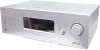
SERVICE MANUAL Ver. 1.1 2007.03 STR-K790 US Model Canadian Model AEP Model UK Model • STR-K790 is the tuner and the amplifier section in HT-DDW790 and HT-DDW795. This receiver incorporates Dolby* Digital and Pro Logic Surround and the DTS** Digital Surround System. * Manufactured under license - Sony STR-K790 | Service Manual - Page 2
STR-K790 Power consumption Area code Power consumption US 210 W Canadian 290 VA AEP, UK 220 W Power consumption (during standby mode) 0.3 W Dimensions (w/h/d) (Approx.) 429 × 145 × 308 mm (16 7/8 × 5 6/8 × 12 1/8 inches) including projecting parts and controls Mass (Approx.) 7.4 kg (16 lb - Sony STR-K790 | Service Manual - Page 3
STR-K790 About area codes The area code of the receiver you purchased is shown on the lower right portion of the rear panel (see the illustration below). RL RL CENTER FRONT SPEAKERS Area code Any differences in operation, according to the area code, are clearly indicated in the text, for example, - Sony STR-K790 | Service Manual - Page 4
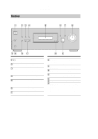
STR-K790 Receiver Front panel 1 234 ?/1 VIDEO 1 IN/ PORTABLE AUDIO IN/ AUTO CAL MIC DIMMER of all speakers at the same time. Turn to select the input source to playback. Receives signals from remote commander. Press to select sound fields (MOVIE, MUSIC). Press to select A.F.D. mode. Connects - Sony STR-K790 | Service Manual - Page 5
"RDS" appears for models of area code AEP, UK only. Lights up when using the receiver to tune in radio stations you have preset. For details on presetting radio stations. Lights up when dynamic range compression is activated. Lights up when DVD input is selected. However, "UNLOCK" appears on the - Sony STR-K790 | Service Manual - Page 6
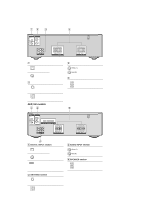
STR-K790 Rear panel US, Canadian models 12 3 4 DIGITAL OPTICAL VIDEO 2/ BD IN COAXIAL DVD IN ANTENNA AM L R AUDIO IN AUDIO IN AUDIO IN SA-CD/CD TV SAT RL SUB RL WOOFER SURROUND SPEAKERS RL RL CENTER FRONT SPEAKERS A DIGITAL INPUT section OPTICAL Connects to a DVD IN jack player, etc - Sony STR-K790 | Service Manual - Page 7
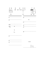
the receiver and to control the Sony audio/video components that the remote is assigned to operate. RM-AAU013 wd ws wa w; ql qk qj qh qg TV INPUT AUTO TV ?/1 SLEEP CAL AV ?/1 ?/1 SYSTEM STANDBY VIDEO 1 VIDEO 2 VIDEO 3 DVD SAT TV SA-CD/CD TUNER 2CH A.F.D. MOVIE MUSIC AMP MENU 123 FM MODE - Sony STR-K790 | Service Manual - Page 8
STR-K790 Name Function D 2CH Press to select 2CH STEREO mode. A.F.D. Press to select A.F.D. mode. MOVIE, MUSIC Press to select sound fields (MOVIE, MUSIC). E AMP MENU Press to display the menu of the receiver. Then, use V, v, B, b and to perform menu operations. F FM MODE all speakers at - Sony STR-K790 | Service Manual - Page 9
may not work depending on the model. • The above explanation is intended to serve as an example only. Therefore, depending on the component, the above operation may not be possible or may operate differently than described. • The VIDEO 3 button on the remote is not available for receiver operation - Sony STR-K790 | Service Manual - Page 10
STR-K790 SECTION 2 TEST MODE SOUND FIELD CLEAR MODE The preset sound field is cleared when this mode is activated. Use this mode model name, destination and the software version are displayed. KEY CHECK MODE MODE The signal will be swapped to all channels so that all speakers CONTROL TEST MODE The - Sony STR-K790 | Service Manual - Page 11
problem 2. DCAC board Checking Connect front left speaker of the receiver and AUTO CAL microphone. Turn MASTER VOLUME jog, there will be test tone sound output from front left speaker, and the display will change accordingly. "AD[]-[]xxx" xxx = 0 to 255 (depends on loudness of test tone) STR-K790 - Sony STR-K790 | Service Manual - Page 12
STR-K790 Ver. 1.1 TUNER SECTION [FM Auto Stop Check] SET SECTION 3 ELECTRICAL ADJUSTMENT generator OUT (75 Ω) Procedure: 1. Turn the power on of A, B and C are detected and automatic scanning stops. The stop of automatic scanning means "The station signal is received in good condition." 12 - Sony STR-K790 | Service Manual - Page 13
. C Q These are omitted. BE BCE These are omitted. • Circuit Boards Location STANDBY board POWER board DCAC board HEADPHONE board DISPLAY board STR-K790 HDMI SW board (AEP,UK) HDMI BRIDGE board (AEP,UK) DIGITAL board MAIN board • Waveforms - DIGITAL Board - 1 IC1905 9 (MCLK1) 72 ns - Sony STR-K790 | Service Manual - Page 14
DIGITAL AUDIO I/F RECEIVER XMCK 20 5 DIN2 12 13 14 15 BST_SEL BST ADCC_INT PCM1609/1803_RST PCM1609_ML PCM1609_MC PCM1609_MDI PCM1609_MDO DATA0 GP9 GP12 HD OUT HD IN HCLK HCS HACN PM XRST CKSEL1 XMODE XSTATE ERROR CE CLK DI DO HDMI_PRE HDMI_OED IC1101(1/2) SYSTEM CONTROL STR-K790 14 14 - Sony STR-K790 | Service Manual - Page 15
CAL MIC IC2000 5 AMP 1 Q2001,2002 DC +7V CONTROL 68 38 Q881-883 PROTECT SWITCH D841 VACS CONTROL 61 45 PROTECTOR VAX CTRL DC-CONTROL ADCC X1101 24MHz IC102 REMOTE CONTROL 1 RECEIVER 82 X0 83 X1 54 SIRCS SYSTEM CONTROL IC1101(2/2) FL_LAT FL_CLK FL_DATA 9 16 17 IC101 BUFFER IC100 - Sony STR-K790 | Service Manual - Page 16
BOARD (SIDE A) - • See page 13 for Circuit Boards Location. :Uses unleaded solder. 1 2 3 4 5 6 7 8 A DIGITAL BOARD (SIDE A) R1943 C1913 B C D E STR-K790 R1096 FB1350 R1318 C1315 R1321 R1253 FB1306 IC1301 R1313 R1312 R1311 R1555 C1031 FB1310 C1301 R1557 RB1500 C1302 R1301 - Sony STR-K790 | Service Manual - Page 17
Ref. No. Location D1003 D-3 D1004 D-3 D1107 C-6 D1108 C-6 D1110 C-6 D1111 C-7 D1501 C-3 D1502 C-3 D1503 D-3 IC1001 E-3 IC1031 B-7 IC1351 C-2 IC1901 B-7 IC1902 B-5 IC1904 B-6 STR-K790 DIGITAL BOARD (SIDE B) STANDBY BOARD C CNP801 (Page 26) AM TUNER FM 75 COAXIAL AEP,UK HDMI BRIDGE A BOARD - Sony STR-K790 | Service Manual - Page 18
40 41 42 43 44 R1314 10k IC1301 DIGITAL AUDIO I/F RECEIVER IC1301 LC89056W-E IC B/D DI DOUT ERROR BPSYNC AUTO_VREF DGND DVDD F3/P3/C3_VF/DATA02 F2/P2/ 0 R1325 0 R1310 1M C1309 18p X1301 12.288MHz C1310 18p R1311 100 J K STR-K790 80 85 86 87 84 9 DIGITAL BOARD (3/5) (Page 20) 18 18 - Sony STR-K790 | Service Manual - Page 19
- DIGITAL BOARD (2/5) - • See page 13 for Waveform. • See page 36 for IC Block Diagram. STR-K790 1 2 3 4 5 6 7 8 9 10 11 12 13 14 15 16 17 18 19 DIGITAL BOARD (4/5) 11 A (Page 21) DIGITAL BOARD (5/5) 12 (Page 22) 79 74 75 73 72 76 5678 69 GP10 0.3 A13 0.3 A14 0.3 A15 - Sony STR-K790 | Service Manual - Page 20
STR-K790 4-7. SCHEMATIC DIAGRAM - DIGITAL BOARD (3/5) - • See page 35, 36 for IC Block Diagrams. 1 A B C D E F G H F MAIN BOARD (1/4) I CNP501 (Page 27) J K 2 3 4 5 6 7 8 9 10 11 12 9 DIGITAL BOARD (1/5) (Page 18) 80 84 85 86 87 DIGITAL BOARD (3/5) C LINK_L AGND C LINK_R T.L OUT - Sony STR-K790 | Service Manual - Page 21
4-8. SCHEMATIC DIAGRAM - DIGITAL BOARD (4/5) - STR-K790 1 2 3 4 5 6 7 8 9 10 11 MAIN BOARD STANDBY (3/4) BOARD A CNP504 D (Page 29) CNP801 CL033 16 GND 15 GND CL028 14 +3.3V(STDBY) CL029 13 +5V 12 VOL_JOG_2A 11 VOL_JOG_2B 10 PW_SW 9 SIRCS 8 AD2 7 AD1 CL030 6 FL_LAT - Sony STR-K790 | Service Manual - Page 22
3.3 93 XMODE 0 94 CKSEL1 0 95 CLK 0 96 CE 0 97 DI 3.2 98 D0 3.2 99 ERROR 3.3 100 XSTATE IC1101 SYSTEM CONTROLLER IC1101 MB90F045PF-G-9033-SPE1 MD1 MD0 STOP TUNER DATA TUNER CLK VAX CTRL MODEL TUNER SD 3.3 R1635 10k 50 3.3 49 0 48 0 R1118 1k 47 0 R1117 1k 46 C1255 - Sony STR-K790 | Service Manual - Page 23
R5055 R5056 R5026 R5072 R5024 R5061 R5060 R5014 R5029 D HDMI BRIDGE BOARD 13 12 CNS199 E 6 CN199 1 A DIGITAL BOARD CNS509 (Page 17) 2 • Semiconductor Location Ref. No. IC5001 IC5002 IC5003 IC5004 IC5005 IC5006 Location C-3 C-4 C-4 B-4 B-4 C-2 1 F STR-K790 B199 1-873-511- 23 23 - Sony STR-K790 | Service Manual - Page 24
• See page 37 for IC Block Diagrams. AEP,UK VIDEO 2/BD IN STR-K790 HDMI SW BOARD R5047 0 R5068 100k TP5016 R5016 0 R5017 0 CN5001 19P CN5002 R5060 0 R5024 0 R5072 100 HDMI BRIDGE BOARD CN199 7P 1 2 CL199 3 4 5 6 CNS199 13P 13 12 11 10 9 8 7 6 5 4 3 2 1 HDMI 6.8V S1(HDMI) GND(NC) OED(HDMI - Sony STR-K790 | Service Manual - Page 25
STR-K790 Ver. 1.1 1 A B C DCAC E BOARD CN2001 (4pin-6pin) (Page 33) D DIGITAL F BOARD CNS501 (Page 17) E DIGITAL G F BOARD CNS502 (Page 17) G H 2 3 4 5 6 7 8 9 10 11 12 RR16 TM604 CC15 CC14 RR15 RR14 JWH17 AEP,UK JW950 SPEAKERS IMPEDANCE USE 6-16 CENTER FRONT R L JW830 JWH19 - Sony STR-K790 | Service Manual - Page 26
872-417- CNP906 5 6 MAIN N BOARD CNP907 (Page 25) MAIN M BOARD CNP902 (Page 25) MAIN BOARD O CNP916 (Page 25) C DIGITAL BOARD CNP505 (Page 17) STR-K790 26 26 7 8 T901 POWER TRANSFORMER • Semiconductor Location Ref. No. D901 D910 D911 D912 D913 D914 D915 D920 D921 D922 D923 Location - Sony STR-K790 | Service Manual - Page 27
CC53 100P CC04 100P CC54 100P R451 1k R402 1k R452 1k R403 1k R453 1k R404 1k R454 1k CNP501 15P STR-K790 F DIGITAL BOARD (3/5) CNS501 (Page 20) CNP502 11P G DIGITAL BOARD (5/5) CNS502 (Page 22) 20 MAIN BOARD (3/4) TP1 (Page 29) 0 0 0 0 0 0 0 0 0 0 C484 0.1 -7 0.9 0.9 C402 10 - Sony STR-K790 | Service Manual - Page 28
STR-K790 4-15. SCHEMATIC DIAGRAM - MAIN BOARD (2/4), STANDBY BOARD - (Page 29) (Page 27) C DIGITAL BOARD (4/5) CNP505 (Page 21) C823 47 25V +7V REG 7 IC821 10EDB40-TA2B5 D913 10EDB40-TA2B5 D914 1SS133T-72 D915 1SS133T-72 C912 0.22 R900 3.3M G901 No mark:FM (CHASSIS) AC IN STR-K790 28 28 - Sony STR-K790 | Service Manual - Page 29
BOOSTER D751 1SS133T-72 R718 22k R719 22k 4.1 Q707 2SC1815 GR-TPE2 AF POWER PROTECT D729 1SS133T-72 R740 100k (Page 28) RY701 RELAY 12V R724 82 D703 2k CNP504 5P L SURROUND R SPEAKERS IMPEDANCE USE 6-16 SUB WOOFER D DIGITAL BOARD (4/5) CNP506 (Page 21) No mark:FM STR-K790 29 29 - Sony STR-K790 | Service Manual - Page 30
-72 R616 3.3k R617 15k C615 10 50V R618 22k R619 22k 4.1 0 Q607 2SC1815 GR-TPE2 AF POWER PROTECT R609 100 C612 -1 47p 500V C662 47p 500V -1.1 R659 100 0 Q604 MP1620 -OPY-MK -37 -37 0.01 CC12 0.01 CC13 0.01 TM602 FRONT SPEAKERS IMPEDANCE USE 6-16 CENTER No mark:FM STR-K790 30 30 - Sony STR-K790 | Service Manual - Page 31
BOARD - • See page 13 for Circuit Boards Location. :Uses unleaded solder. STR-K790 1 2 3 4 5 6 7 8 A DISPLAY BOARD CL125 B K CN101 S104 DISPLAY R103 S103 AUTO CAL RV101 INPUT SELECTOR JW152 JW116 11 12 13 14 MASTER VOLUME RV102 C150 JW101 JW153 JW139 CL103 CL104 C107 - Sony STR-K790 | Service Manual - Page 32
IC102 REMOTE CONTROL RECEVER RPM7240 12 FL_LAT 13 FL_DI N 14 FL_CLK 15 INPUT_JOG_4A 16 INPUT_JOG_4B 17 DCAC_IN I MAIN BOARD (2/4) CNP908 (Page 28) H DIGITAL BOARD (4/5) CNS513 (Page 21) CNP102 2P 1 DCAC_IN (CN2001) 2 DC-CONTROL (CN2001) L DCAC BOARD CN2001 (Page 34) No mark : FM STR-K790 - Sony STR-K790 | Service Manual - Page 33
BOARD - • See page 13 for Circuit Boards Location. :Uses unleaded solder. STR-K790 1 2 3 A POWER BOARD B C S152 D JW123 JW122 JW121 E F R135 S115 R136 S116 SLEEP 2CH K DISPLAY BOARD CN101 (Page 31) 10 11 12 13 14 15 DCAC BOARD J2000 VIDEO 1 IN/ PORTABLE AUDIO IN/ AUTO CAL - Sony STR-K790 | Service Manual - Page 34
CNP732) 6 +/-7V GND (CNP732) 5 +7V (CNP732) 4 DC-CONTROL 3 BLANK 2 DCAC_OUT (CN102) 1 DCAC BOARD CL2002 CL2001 CL2005 CL2003 C 56p R2010 10k C2010 0.033 R2007 10k No mark : FM 9 10 11 12 13 HEADPHONE BOARD J MAIN BOARD (4/4) CN701 (Page 30) CNP790 4P HP_DETECT 1 STR-K790 34 34 - Sony STR-K790 | Service Manual - Page 35
STR-K790 • IC Block Diagrams - DIGITAL Board - IC1301 LC89056W-E DI DO ERROR 46 CKSEL1 47 XMODE 48 MICROCOMPUTER INTERFACE MODE SELECT SYSTEM RESET SAMPLING FREQUENCY LOCK DETECT DATA DEMODULATOR Cut Filter Serial Interface Mode/ Format Control Clock and Timing Control 20 MODE1 19 MODE0 18 - Sony STR-K790 | Service Manual - Page 36
STR-K790 SYSTEM CLOCK MANAGER FUNCTION CONTROL INTERFACE SYSTEM CLOCK SERIAL INPUT INTERFACE 4X/8X OVER SAMPLING DIGITAL FILTER WITH FUNCTION CONTROLLER ZERO DETECT DAC DAC DAC ENHANCED MULTI- DAC LEVEL DELTA- SIGMA MOJULATOR DAC DAC DAC DAC selector INR1 11 AVEE 12 ADIFL 13 ADIFR - Sony STR-K790 | Service Manual - Page 37
STR-K790 - HDMI SW Board - IC5001 TMDS341PFCR VCC GND A14 B14 VCC A13 B13 GND Drive TMDS Drive HPD_SINK 40 18 17 16 15 14 13 12 11 10 9 8 7 6 5 4 3 2 1 (3.3V) VCC RINT Rx w/ EQ VCC RINT Rx w/ EQ VCC RINT Rx w/ EQ VCC RINT Rx w/ EQ 3-to-1 MUX Control Logic (3.3V) VCC RINT Rx w/ EQ VCC RINT - Sony STR-K790 | Service Manual - Page 38
STR-K790 - DISPLAY Board - IC100 PT6315 VSS VDD GRID1 GRID2 GRID3 GRID4 SEG24/GRID5 SEG23/GRID6 SEG22/GRID7 SEG21/GRID8 SEG20/GRID9 LED1 1 LED2 2 LED3 3 LED4 4 4-bit latch 44 43 42 41 40 39 Grid driver Command decoder Display memory 24 bits x 12 words 38 37 36 35 34 Multiplexed driver 33 - Sony STR-K790 | Service Manual - Page 39
MB90F045PF-G-9033-SPE1 (SYSTEM CONTROLLER) Pin No. 1 2 3 4 5 6 7 8 9 10 11 12 13 14 15 16 DAC and ADC - Ground terminal O Latch signal output to DAC O Clock signal output to DAC O IC data output to DAC I IC data input from DAC AEP, UK only) I MODEL select input I Vacs control input STR-K790 39 - Sony STR-K790 | Service Manual - Page 40
STR-K790 Pin No. Pin Name I/O Description 46 TUNER CLK O Tuner clock signal output 47 TUNER DATA O Tuner data signal output 48 STOP I AC off detect signal input 49 MD0 I Operation mode setting input 50 MD1 I Operation mode setting input 51 MD2 I Operation mode setting input 52 - Sony STR-K790 | Service Manual - Page 41
Pin No. 95 96 97 98 99 100 Pin Name CLK CE DI DO ERROR XSTATE I/O Description O Clock signal output to DIR O Chip enable signal output to DIR O Data signal output to DIR I Data signal input from DIR I PLL error muting signal input from DIR I XSTATE data signal input from DIR STR-K790 41 - Sony STR-K790 | Service Manual - Page 42
STR-K790 SECTION 5 EXPLODED VIEWS NOTE: • -XX and -X mean standardized parts, not stocked since they are seldom required for routine service. Some delay should be anticipated when ordering these items. • Abbreviation CND : Canadian model 5-1. FRONT PANEL SECTION The components identified by mark - Sony STR-K790 | Service Manual - Page 43
STR-K790 Ver. 1.1 5-2. CHASSIS SECTION 53 not supplied #1 Q554 Q654 not supplied UK) 1-828-971-11 WIRE (FLAT TYPE) (13 CORE) (AEP, UK) A-1158-394-A HDMI SW BOARD, COMPLETE (AEP, UK) 4-956-370-12 BAND, PLUG FIXED (UK) 1-693-728-11 TUNER (FM/AM) (CND) Ref. No. 65 65 0 F901 0 F901 0 Q503 0 Q504 0 - Sony STR-K790 | Service Manual - Page 44
STR-K790 are not stocked since they are seldom required for routine service. Some delay should be anticipated when ordering these items. µPC. . uPD. . : µPD. . • Abbreviation CND : Canadian model When indicating parts by reference number, please include the board name. The components identified - Sony STR-K790 | Service Manual - Page 45
STR-K790 DIGITAL Ref. No. Part No. Description Remark C1172 1-162-974-11 CERAMIC CHIP 0.01uF 50V C1253 1-162-960-11 CERAMIC CHIP 220PF 10% 50V C1254 1- - Sony STR-K790 | Service Manual - Page 46
STR-K790 DIGITAL Ref. No. Part No. Description Remark Ref. No. Part No. Description 759-096-87 IC TC7WU04FU (TE12R) R1096 1-216-833-11 METAL CHIP 10K IC1351 6-600-466-01 IC TORX147L (SONY) (DIGITAL/OPTICAL/VIDEO 2,BD IN) R1105 1-216-833-11 METAL CHIP 10K IC1401 6-707-608-01 IC PCM1803DBR - Sony STR-K790 | Service Manual - Page 47
STR-K790 DIGITAL Ref. No. R1179 R1180 R1181 Part No. Description 1-216-833-11 METAL CHIP 1-216-833-11 METAL CHIP 1-216-833-11 METAL CHIP R1182 - Sony STR-K790 | Service Manual - Page 48
STR-K790 DIGITAL DISPLAY HDMI SW Ref. No. Part No. Description < NETWORK F 1/4W F < VIBRATOR > X1101 1-813-448-21 PIEZOELECTRIC OSCILLATOR (24MHz) X1301 1-795-126-21 VIBRATOR, CRYSTAL (12.288MHz) X1502 1-813-276-21 QUARTZ CRYSTAL (13.9MHz S103 1-771-410-21 SWITCH, TACTILE (AUTO CAL) S104 - Sony STR-K790 | Service Manual - Page 49
STR-K790 HDMI SW HDMI_BRIDGE HEADPHONE MAIN Ref. No. Part No. Description < COIL > L5013 1-400-862-11 BEAD, FERRITE < RESISTOR > R5001 1-218-861-11 METAL CHIP 3.9K - Sony STR-K790 | Service Manual - Page 50
STR-K790 MAIN Ref. No. C556 C557 C558 C561 Part No. Description 1-107-583-11 CERAMIC 1-104-658-91 ELECT 1-126-947-11 ELECT 1-162-815-11 - Sony STR-K790 | Service Manual - Page 51
STR-K790 Ver. 1.1 MAIN Ref. No. Part No. Description < CONNECTOR > Remark CNP501 1-573-847-11 CONNECTOR, BOARD TO BOARD (PLUG) 15P CNP502 1-573-843-11 CONNECTOR, BOARD - Sony STR-K790 | Service Manual - Page 52
STR-K790 MAIN Ref. No. R454 R471 R472 R473 Part No. Description 1-247-831-91 CARBON 1-249-415-11 CARBON 1-247-831-91 CARBON 1-249-421-11 - Sony STR-K790 | Service Manual - Page 53
STR-K790 MAIN POWER Ref. 12 RELAY 1-755-416-12 RELAY 1-755-416-12 RELAY < TERMINAL > 5% 1/4W F (AEP, UK) 1/4W F 1/4W F 1/4W 1/4W F 1/4W 1/4W 1/4W 1/4W 1/4W TM600 1-694-805-11 TERMINAL BOARD (FRONT,CENTER/SPEAKERS IMPEDANCE 6-16Ω) TM602 1-694-805-11 TERMINAL BOARD (SURROUND,SUB WOOFER/ SPEAKERS - Sony STR-K790 | Service Manual - Page 54
STR-K790 Ver. 1.1 STANDBY Ref. No. Part No. Description Remark A-1221-175-A STANDBY BOARD, COMPLETE FM/AM) (AEP, UK) FUSE (T2.5AL/250V) (AEP, UK) 0 F901 0 Q503 0 Q504 0 Q553 0 Q554 1-533-452-12 6-702-390-01 6-702-391-01 6-702-390-01 6-702-391-01 FUSE, GLASS TUBE (DIA. 5) (4A/125V) (US, CND) - Sony STR-K790 | Service Manual - Page 55
MEMO STR-K790 55 - Sony STR-K790 | Service Manual - Page 56
STR-K790 REVISION HISTORY Clicking the version allows you to jump to the revised page. Also, clicking the version at the 1.0 2007.02 New 1.1 2007.03 Change of FM Auto Stop Check Change of Part No. of TUNER for US model Addition of D884 to MAIN board (SPM-07002) (ECN-ECC03280) (ENG-07004)
-
 1
1 -
 2
2 -
 3
3 -
 4
4 -
 5
5 -
 6
6 -
 7
7 -
8
-
9
-
10
-
11
-
12
-
13
-
14
-
15
-
16
-
17
-
18
-
19
-
20
-
21
-
22
-
23
-
24
-
25
-
26
-
27
-
28
-
29
-
30
-
31
-
32
-
33
-
34
-
35
-
36
-
37
-
38
-
39
-
40
-
41
-
42
-
43
-
44
-
45
-
46
-
47
-
48
-
49
-
50
-
51
-
52
-
53
-
54
-
55
-
56
 |
 |

SERVICE MANUAL
Sony Corporation
Home Audio Division
Published by Sony Techno Create Corporation
US Model
Canadian Model
AEP Model
UK Model
FM STEREO/FM-AM RECEIVER
9-887-542-02
2007C16-1
© 2007.03
Ver. 1.1
2007.03
SPECIFICATIONS
STR-K790
•
STR-K790 is the tuner and the amplifier section
in HT-DDW790 and HT-DDW795.
This receiver incorporates Dolby* Digital and Pro Logic Surround and
the DTS** Digital Surround System.
*
Manufactured under license from Dolby Laboratories.
“Dolby”, “Pro Logic” and the double-D symbol are trademarks of
Dolby Laboratories.
**
“DTS” and “DTS Digital Surround” are registered trademarks of DTS,
Inc.
— Continued on next page —
AUDIO POWER
SPECIFICATIONS
POWER OUTPUT AND TOTAL
HARMONIC DISTORTION:
(Models of area code US only)
With 6 ohm loads, both channels driven, from
120 – 20,000 Hz; rated 85 watts per channel
minimum RMS power, with no more than 1%
total harmonic distortion from 250 milliwatts
to rated output.
Amplifier section
Power Output
1)
Stereo mode (rated) (6 ohms 1 kHz, THD 1%)
85 W + 85 W
Surround mode
2)
(reference)
(6 ohms 1 kHz, THD 10%)
RMS output
FRONT:133 W
per channel
CENTER: 133 W
SURROUND: 133 W
per channel
Surround mode
2)
(reference)
(6 ohms 100 Hz, THD 10%)
SUB WOOFER: 135 W
1)
Measured under the following conditions:
Area code
Power requirements
US, Canadian
120 V AC, 60 Hz
AEP, UK
230 V AC, 50 Hz
2)
Reference power output for front, center, surround
speakers and sub woofer. Depending on the sound
field settings and the source, there may be no
sound output.
Inputs
Analog
Sensitivity: 800 mV/
50 kohms
Digital (Coaxial)
Impedance: 75 ohms
Tone
Gain levels
±
6 dB, 1 dB step
Reproduction frequency range:
28 – 20,000 Hz
FM tuner section
Tuning range
87.5 - 108.0 MHz
Antenna
FM wire antenna
Antenna terminals
75 ohms, unbalanced
Intermediate frequency
10.7 MHz
AM tuner section
Tuning range
Models of area code US, Canadian
With 10-kHz tuning scale:
530 – 1,710 kHz
4)
With 9-kHz tuning scale:
531 – 1,710 kHz
4)
Models of area code AEP, UK
With 9-kHz tuning scale:
531 – 1,602 kHz
Antenna
Loop antenna
Intermediate frequency
450 kHz
4)
You can change the AM tuning scale to 9 kHz or
10 kHz. After tuning in any AM station, turn off
the receiver. While holding down DIMMER, press
?/1
. All preset stations will be erased when you
change the tuning scale. To reset the scale to 10
kHz (or 9 kHz), repeat the procedure.
General
Power requirements
Area code
Power requirements
US, Canadian
120 V AC, 60 Hz
AEP, UK
230 V AC, 50/60 Hz