Sony SU-WL810 Operating Instructions SU-WL810 Wall Mount
Sony SU-WL810 Manual
 |
View all Sony SU-WL810 manuals
Add to My Manuals
Save this manual to your list of manuals |
Sony SU-WL810 manual content summary:
- Sony SU-WL810 | Operating Instructions SU-WL810 Wall Mount - Page 1
Wall-Mount Bracket Operating Instructions US Manuel d'instructions FR Manual de instrucciones ES SU-WL810 4-588-644-13(1) - Sony SU-WL810 | Operating Instructions SU-WL810 Wall Mount - Page 2
If the Wall-Mount Bracket is removed after installing it on the wall, the screw holes are left. Do not use the Wall-Mount Bracket in a place where it is subjected to mechanical vibrations. Installing the WallMount Bracket To Sony Dealers WARNING The following instructions are for Sony dealers only - Sony SU-WL810 | Operating Instructions SU-WL810 Wall Mount - Page 3
install the Wall-Mount Bracket securely to the wall following the instructions in this instruction manual. If any of the screws are loose or fall out, the Wall-Mount Bracket may fall and cause injury or property damage. Be sure to use the appropriate screws for the material of the wall and install - Sony SU-WL810 | Operating Instructions SU-WL810 Wall Mount - Page 4
or Concrete Block 15 Specifications ...19 Before getting started Firstly, check the type of the wall to install the TV. The Wall-Mount Bracket differs depending on the type of the wall. What is your wall made of? Dry wall with studs Solid Concrete or Concrete Block Precautions Maximum dry - Sony SU-WL810 | Operating Instructions SU-WL810 Wall Mount - Page 5
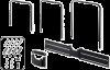
inch x 2 3/8 inch) (4) 4.8 mm x 32 mm (7/32 inch x 1 5/16 inch) (2) WW1 WA1 Tools needed *1 WW2 (4) WA2 (4) US (2) (2) 5.5 mm (7/32 inch) 10 mm (3/8 inch) *2 *1 Only for dry wall with studs *2 Only for solid concrete or concrete block US 5 - Sony SU-WL810 | Operating Instructions SU-WL810 Wall Mount - Page 6
Preparing for the 2 installation of the TV 1 Put the TV on the Table-Top Stand to prepare the installation of the Wall-Mount Bracket. M5L12 SN 75 65 CL(S) 55 SN SB 2 1 SB CC SC SN M5L12 x 4 US 6 - Sony SU-WL810 | Operating Instructions SU-WL810 Wall Mount - Page 7
3 5 x 4 M5L12 6 Remove the screws from the 4 rear of the TV. US 7 Choose the U-shaped Bar according to your TV inch size. 75 65 55 UB 75 UB 75 UB 65 UB 65 UB 55 UB 55 US 7 - Sony SU-WL810 | Operating Instructions SU-WL810 Wall Mount - Page 8
8 Attach U-shaped Bar to the rear of the TV. UB 75 65 55 M6L20 1.5 N∙m/1,5 N∙m {15 kgf∙cm} previously removed 1.5 N∙m/1,5 N∙m {15 kgf∙cm} US 8 - Sony SU-WL810 | Operating Instructions SU-WL810 Wall Mount - Page 9
9 WM3 WM5 * * Only for lateral shift bracket WM4 10 Connect and bundle the cables. 1 2 3 US US 9 - Sony SU-WL810 | Operating Instructions SU-WL810 Wall Mount - Page 10
Attaching the Lateral Shift Bracket to the Dry Wall with Studs Dry wall with studs WM4 1 Decide on the installation location. Make sure that the wall has enough space for the TV and is capable of supporting a weight of at least four times that of the TV. A E F C B D XBR 75X940D 65X930D - Sony SU-WL810 | Operating Instructions SU-WL810 Wall Mount - Page 11
2 406 mm (16 inch) / 610 mm (24 inch) 4 Poke through TM with a pencil to make marks on the wall. WM4 1 0 2 3 50 4 100 150 200 55'' 250 300 350 75'' 400 3 0 50 12inch 11inch 10inch 9inch 8inch 7inch 6inch 5inch 4inch 3inch 2inch 1inch 0 100 - Sony SU-WL810 | Operating Instructions SU-WL810 Wall Mount - Page 12
5 75 mm 7 (3 inch) 5.5 mm (7/32 inch) 1, 2, 3, 4 12inch 11inch 10inch 9inch 8inch 7inch 6inch 5inch 4inch 3inch 2inch 1inch 0 0 50 100 150 200 250 55" 300 65" 350 75" 400 0 1inch 2inch 3inch 4inch 5inch 6inch 7inch 8inch 9inch 10inch 11inch 12inch Note Be sure to drill into the - Sony SU-WL810 | Operating Instructions SU-WL810 Wall Mount - Page 13
9 WS1 11 WM4 WW1 Precaution Do not over-tighten the lag bolts WS1 . Improper tightening could reduce the holding power of the lag bolts WS1 . 10 x 4 M5L12 WM4 WM1 US WM1 WM4 WM4 US 13 - Sony SU-WL810 | Operating Instructions SU-WL810 Wall Mount - Page 14
12 CL(S) 13 US 14 - Sony SU-WL810 | Operating Instructions SU-WL810 Wall Mount - Page 15
Attaching the Wall-Mount Bracket to the Solid Concrete or Concrete Block Solid Concrete or Concrete Block WM2 1 Decide on the installation location. Make sure that the wall has enough space for the TV and is capable of supporting a weight of at least four times that of the TV. A E F US C B - Sony SU-WL810 | Operating Instructions SU-WL810 Wall Mount - Page 16
2 3 TM 1 0 2 3 50 4 100 150 200 55'' 250 300 65'' 350 75'' 400 TM 4 75 mm (3 inch) 10 mm (3/8 inch) 1 0 2 3 50 4 100 150 200 55'' 250 300 65'' 350 75'' 400 1, 2, 3, 4 1 0 2 3 50 4 100 150 200 55'' 250 300 65'' 350 75'' 400 US 16 - Sony SU-WL810 | Operating Instructions SU-WL810 Wall Mount - Page 17
5 7 x 4 WA1 M5L12 8 6 US WS1 Precaution Do not over-tighten the lag bolts WS1 . Improper tightening could reduce the holding power of the lag bolts WS1 . WM2 WM1 WM1 WM2 WM2 US 17 - Sony SU-WL810 | Operating Instructions SU-WL810 Wall Mount - Page 18
9 CL(S) 10 US 18 - Sony SU-WL810 | Operating Instructions SU-WL810 Wall Mount - Page 19
Specifications WM4 bc WM2 a d e j g c h i Dimension: (Approx.) (mm (inch)) a: 1,050 mm (41 3/8 inch) b: 147 mm (5 7/8 inch) c: 70 mm (2 7/8 inch) d: 179 mm (7 1/8 inch) e: 1,021 mm (40 1/4 inch) f: 26 mm (1 1/16 inch) g: 156 mm (6 1/4 inch) h: 200 mm (7 7/8 inch) i: 219 mm (8 5/8 inch) j: 20 mm ( - Sony SU-WL810 | Operating Instructions SU-WL810 Wall Mount - Page 20
fixation murale à un endroit soumis à des vibrations mécaniques. Installation du support de fixation murale Aux détaillants Sony AVERTISSEMENT Les instructions suivantes sont destinées uniquement aux détaillants Sony. Lisez attentivement les consignes de sécurité ci-dessus et accordez une attention - Sony SU-WL810 | Operating Instructions SU-WL810 Wall Mount - Page 21
d'air provenant du climatiseur pourrait provoquer un incendie, l'électrocution ou des problèmes de fonctionnement du téléviseur. Veillez à installer le support de fixation murale solidement au mur en suivant les instructions présentes dans ce mode d'emploi. Si une vis se desserre ou tombe, le - Sony SU-WL810 | Operating Instructions SU-WL810 Wall Mount - Page 22
bloc de béton 15 Spécifications ...19 Avant de commencer Commencez par vérifier le type de matériau du mur sur lequel vous souhaitez installer le téléviseur. Le support de fixation murale varie selon le type de mur. Quel est le type de matériau du mur? Cloison sèche avec montants Béton - Sony SU-WL810 | Operating Instructions SU-WL810 Wall Mount - Page 23
Accessoires fournis WM1 WM2 WM3 WM4 WM5 UB 75 UB 75 UB 65 UB 65 UB 55 UB 55 TM M6L20 LIMITED WARRANTY WS1 WS2 8 mm x 60 mm (11/32 pouces x 2 3/8 pouces) (4) WW1 4,8 mm x 32 mm (7/32 pouces x 1 5/16 pouces) (2) WA1 Outils requis *1 WW2 (4) WA2 (4) (2) FR FR (2) 5,5 mm (7/32 - Sony SU-WL810 | Operating Instructions SU-WL810 Wall Mount - Page 24
Préparation pour 2 l'installation du téléviseur 1 Placez le téléviseur sur le support de table pour préparer l'installation du support de fixation murale. M5L12 SN 75 65 CL(S) 55 SN SB 2 1 SB CC SC SN M5L12 x 4 FR 6 - Sony SU-WL810 | Operating Instructions SU-WL810 Wall Mount - Page 25
3 5 x 4 M5L12 6 Retirez les vis situées à l'arrière 4 du téléviseur. FR FR 7 Choisissez la barre en forme de U correspondant à la taille de votre téléviseur. 75 65 55 UB 75 UB 75 UB 65 UB 65 UB 55 UB 55 FR 7 - Sony SU-WL810 | Operating Instructions SU-WL810 Wall Mount - Page 26
8 Fixez la barre en forme de U à l'arrière du téléviseur. UB 75 65 55 M6L20 1.5 N∙m/1,5 N∙m {15 kgf∙cm} que vous avez enlevées précédemment 1.5 N∙m/1,5 N∙m {15 kgf∙cm} FR 8 - Sony SU-WL810 | Operating Instructions SU-WL810 Wall Mount - Page 27
9 WM3 WM5 * FR FR * Uniquement pour le support de déplacement latéral WM4 10 Raccordez et regroupez les câbles. 1 2 3 FR 9 - Sony SU-WL810 | Operating Instructions SU-WL810 Wall Mount - Page 28
sur la Cloison Sèche avec Montants Cloison sèche avec montants WM4 1 Décidez de l'emplacement d'installation. Assurez-vous que le mur offre suffisamment d'espace pour le téléviseur et qu'il peut supporter un poids équivalent à au moins quatre fois celui du téléviseur. A E F C B D XBR 75X940D - Sony SU-WL810 | Operating Instructions SU-WL810 Wall Mount - Page 29
2 406 mm (16 pouces) / 610 mm (24 pouces) 4 Percez le TM avec un crayon pour marquer le mur. WM4 1 0 2 3 50 4 100 150 200 55'' 250 300 350 75'' 400 3 0 50 12inch 11inch 10inch 9inch 8inch 7inch 6inch 5inch 4inch 3inch 2inch 1inch 0 100 150 200 250 55" 300 65" 350 75" 400 0 1inch - Sony SU-WL810 | Operating Instructions SU-WL810 Wall Mount - Page 30
5 75 mm 7 (3 pouces) 5,5 mm (7/32 pouces) 1, 2, 3, 4 12inch 11inch 10inch 9inch 8inch 7inch 6inch 5inch 4inch 3inch 2inch 1inch 0 0 50 100 150 200 250 55" 300 65" 350 75" 400 0 1inch 2inch 3inch 4inch 5inch 6inch 7inch 8inch 9inch 10inch 11inch 12inch Remarque Assurez-vous de - Sony SU-WL810 | Operating Instructions SU-WL810 Wall Mount - Page 31
9 WS1 11 WM4 WW1 Précautions Ne serrez pas excessivement les tirefonds WS1 . Un serrage incorrect pourrait réduire la capacité de maintien des tirefonds WS1 . 10 x 4 M5L12 WM4 WM1 FR WM1 FR WM4 WM4 FR 13 - Sony SU-WL810 | Operating Instructions SU-WL810 Wall Mount - Page 32
12 CL(S) 13 FR 14 - Sony SU-WL810 | Operating Instructions SU-WL810 Wall Mount - Page 33
solide ou bloc de béton Béton solide ou bloc de béton WM2 1 Décidez de l'emplacement d'installation. Assurez-vous que le mur offre suffisamment d'espace pour le téléviseur et qu'il peut supporter un poids équivalent à au moins quatre fois celui du téléviseur. A E F C FR FR B D XBR 75X940D - Sony SU-WL810 | Operating Instructions SU-WL810 Wall Mount - Page 34
2 3 TM 1 0 2 3 50 4 100 150 200 55'' 250 300 65'' 350 75'' 400 TM 4 75 mm (3 pouces) 10 mm (3/8 pouces) 1 0 2 3 50 4 100 150 200 55'' 250 300 65'' 350 75'' 400 1, 2, 3, 4 1 0 2 3 50 4 100 150 200 55'' 250 300 65'' 350 75'' 400 FR 16 - Sony SU-WL810 | Operating Instructions SU-WL810 Wall Mount - Page 35
5 7 x 4 WA1 M5L12 8 6 FR FR WS1 Précautions Ne serrez pas excessivement les tirefonds WS1 . Un serrage incorrect pourrait réduire la capacité de maintien des tirefonds WS1 . WM2 WM1 WM1 WM2 WM2 FR 17 - Sony SU-WL810 | Operating Instructions SU-WL810 Wall Mount - Page 36
9 CL(S) 10 FR 18 - Sony SU-WL810 | Operating Instructions SU-WL810 Wall Mount - Page 37
Spécifications WM4 bc WM2 a d e j g c h i Dimensions : (Environ) (mm (pouces)) a : 1 050 mm (41 3/8 pouces) b : 147 mm (5 7/8 pouces) c : 70 mm (2 7/8 pouces) d : 179 mm (7 1/8 pouces) e : 1 021 mm (40 1/4 pouces) f : 26 mm (1 1/16 pouces) g : 156 mm (6 1/4 pouces) h : 200 mm (7 7/8 pouces) i : - Sony SU-WL810 | Operating Instructions SU-WL810 Wall Mount - Page 38
manual y utilice el producto correctamente. Conserve este manual para poder consultarlo en el futuro. Los productos de Sony del televisor. (Consulte las instrucciones de su televisor para obtener información sobre el ños personales o materiales. No instale ningún equipo diferente al producto - Sony SU-WL810 | Operating Instructions SU-WL810 Wall Mount - Page 39
los costados del TV sobresalgan de la superficie de la pared. No instale el soporte de montaje mural en superficies de paredes, tales como una soporte de montaje mural firmemente a la pared siguiendo las instrucciones de este manual de instrucciones. Si alguno de los tornillos se deja flojo o se cae - Sony SU-WL810 | Operating Instructions SU-WL810 Wall Mount - Page 40
el soporte de montaje mural. Pasos a seguir Conecte el soporte de sobremesa del TV. Coloque la barra en forma de U y los cables al TV. Instale el soporte de desplazamiento lateral en la pared. Separe la mesa auxiliar del TV. Cuelgue el TV en la pared. Pasos a seguir Conecte el soporte - Sony SU-WL810 | Operating Instructions SU-WL810 Wall Mount - Page 41
Artículos suministrados WM1 WM2 WM3 WM4 WM5 UB 75 UB 75 UB 65 UB 65 UB 55 UB 55 TM M6L20 LIMITED WARRANTY WS1 WS2 8 mm x 60 mm (4) 4,8 mm x 32 mm (2) WW1 WA1 Herramientas necesarias *1 WW2 (4) WA2 (4) (2) ES ES (2) 5,5 mm 10 mm *2 *1 Solo para pared de mampostería con pernos de - Sony SU-WL810 | Operating Instructions SU-WL810 Wall Mount - Page 42
Preparación de la 2 instalación del TV 1 Coloque el TV sobre el soporte de sobremesa para preparar la instalación del soporte de montaje mural. M5L12 SN 75 65 CL(S) 55 SN SB 2 1 SB CC SC SN M5L12 x 4 ES 6 - Sony SU-WL810 | Operating Instructions SU-WL810 Wall Mount - Page 43
3 5 x 4 M5L12 6 Quite los tornillos de la parte 4 trasera del TV. ES ES 7 Seleccione la barra en forma de U según el tamaño de su TV. 75 65 55 UB 75 UB 75 UB 65 UB 65 UB 55 UB 55 ES 7 - Sony SU-WL810 | Operating Instructions SU-WL810 Wall Mount - Page 44
8 Coloque la barra en forma de U a la parte trasera del TV. UB 75 65 55 M6L20 1.5 N∙m/1,5 N∙m {15 kgf∙cm} retirados previamente 1.5 N∙m/1,5 N∙m {15 kgf∙cm} ES 8 - Sony SU-WL810 | Operating Instructions SU-WL810 Wall Mount - Page 45
9 WM3 WM5 * * Solo para el soporte de desplazamiento lateral WM4 10 Conecte y agrupe los cables. 1 2 3 ES ES ES 9 - Sony SU-WL810 | Operating Instructions SU-WL810 Wall Mount - Page 46
Una el soporte de desplazamiento lateral a la Pared de Mampostería con Pernos de tope Pared de mampostería con pernos de tope WM4 1 Decida dónde va a realizar la instalación. Asegúrese de que la pared tenga espacio suficiente para el TV y pueda soportar un peso que represente al menos cuatro - Sony SU-WL810 | Operating Instructions SU-WL810 Wall Mount - Page 47
2 3 406 mm / 610 mm 4 Pique con un lápiz a través de TM para hacer marcas en la pared. WM4 1 0 2 3 50 4 100 150 200 55'' 250 300 350 75'' 400 0 50 12inch 11inch 10inch 9inch 8inch 7inch 6inch 5inch 4inch 3inch 2inch 1inch 0 100 150 200 250 55" 300 65" 350 75" 400 0 1inch 2inch - Sony SU-WL810 | Operating Instructions SU-WL810 Wall Mount - Page 48
5 7 75 mm 5,5 mm 1, 2, 3, 4 12inch 11inch 10inch 9inch 8inch 7inch 6inch 5inch 4inch 3inch 2inch 1inch 0 0 50 100 150 200 250 55" 300 65" 350 75" 400 0 1inch 2inch 3inch 4inch 5inch 6inch 7inch 8inch 9inch 10inch 11inch 12inch Nota Asegúrese de perforar en el centro del perno de - Sony SU-WL810 | Operating Instructions SU-WL810 Wall Mount - Page 49
9 WS1 11 WM4 WW1 Precauciones No ajuste demasiado los pernos de fijación WS1 . El ajuste inadecuado puede reducir la capacidad de retención del perno de fijación WS1 . 10 x 4 M5L12 WM4 WM1 WM1 ES ES WM4 WM4 ES 13 - Sony SU-WL810 | Operating Instructions SU-WL810 Wall Mount - Page 50
12 CL(S) 13 ES 14 - Sony SU-WL810 | Operating Instructions SU-WL810 Wall Mount - Page 51
Coloque el soporte de montaje mural al concreto sólido o al bloque de concreto Concreto sólido o bloque de concreto WM2 1 Decida dónde va a realizar la instalación. Asegúrese de que la pared tenga espacio suficiente para el TV y pueda soportar un peso que represente al menos cuatro veces el del - Sony SU-WL810 | Operating Instructions SU-WL810 Wall Mount - Page 52
2 3 TM 1 0 2 3 50 4 100 150 200 55'' 250 300 65'' 350 75'' 400 TM 4 75 mm 10 mm 1 0 2 3 50 4 100 150 200 55'' 250 300 65'' 350 75'' 400 1, 2, 3, 4 1 0 2 3 50 4 100 150 200 55'' 250 300 65'' 350 75'' 400 ES 16 - Sony SU-WL810 | Operating Instructions SU-WL810 Wall Mount - Page 53
5 7 x 4 WA1 M5L12 8 6 ES ES WS1 Precauciones No ajuste demasiado los pernos de fijación WS1 . El ajuste inadecuado puede reducir la capacidad de retención del perno de fijación WS1 . WM2 WM1 WM1 WM2 WM2 ES 17 - Sony SU-WL810 | Operating Instructions SU-WL810 Wall Mount - Page 54
9 CL(S) 10 ES 18 - Sony SU-WL810 | Operating Instructions SU-WL810 Wall Mount - Page 55
Especificaciones WM4 bc WM2 a d e j g c h i Dimensiones: (Aprox.) (mm) a: 1.050 mm b: 147 mm c: 70 mm d: 179 mm e: 1.021 mm f: 26 mm g: 156 mm h: 200 mm i: 219 mm j: 20 mm Peso (solo de la base): (Aprox.) WM4 3 kg WM2 1 kg El diseño y las especificaciones pueden cambiar sin aviso. f ES ES ES 19 - Sony SU-WL810 | Operating Instructions SU-WL810 Wall Mount - Page 56
http://www.sony.net/ 4-588-644-13(1) © 2016 Sony Corporation Printed in China
-
 1
1 -
 2
2 -
 3
3 -
 4
4 -
 5
5 -
 6
6 -
 7
7 -
8
-
9
-
10
-
11
-
12
-
13
-
14
-
15
-
16
-
17
-
18
-
19
-
20
-
21
-
22
-
23
-
24
-
25
-
26
-
27
-
28
-
29
-
30
-
31
-
32
-
33
-
34
-
35
-
36
-
37
-
38
-
39
-
40
-
41
-
42
-
43
-
44
-
45
-
46
-
47
-
48
-
49
-
50
-
51
-
52
-
53
-
54
-
55
-
56
 |
 |

4-588-644-
13
(1)
SU-WL810
Wall-Mount
Bracket
Operating Instructions
US
Manuel d’instructions
FR
Manual de instrucciones
ES