Sony TC-WR720A Service Manual
Sony TC-WR720A - Dual Cassette Deck Manual
 |
View all Sony TC-WR720A manuals
Add to My Manuals
Save this manual to your list of manuals |
Sony TC-WR720A manual content summary:
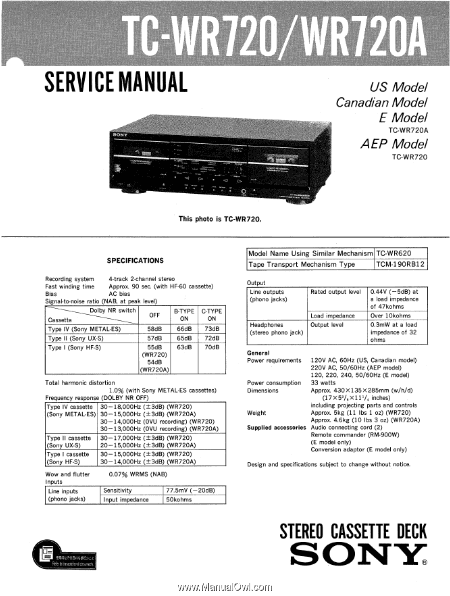
- Sony TC-WR720A | Service Manual - Page 1
SERVICE MANUAL 0> • US Model Canadian Model E Model TC-WR720A AEP Model TC-WR720 This photo is TC-WR720. SPECIFICATIONS Sony METAL-ES) 58dB 66dB 73dB Type II (Sony UX-S) 57dB 65dB 72dB Type I (Sony HF-S) 55dB (WR720) 54dB (WR720A) 63dB 70dB Total harmonic distortion 1.0% (with Sony - Sony TC-WR720A | Service Manual - Page 2
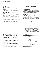
TC-WR720/WR720A SONY PARTS WHOSE PART NUMBERS APPEAR AS SHOWN IN THIS MANUAL OR IN SUPPLEMENTS PUBLISHED BY SONY PUBLIES PAR SONY. SAFETY CHECK-OUT After correcting the original service problem, perform RCA WT-540A. Follow the manufacturers' instructions to use these instruments. A battery-operated - Sony TC-WR720A | Service Manual - Page 3
, WG (West Germany) model SONY® MODEL NO. TC-WR720 STEREO CASSETTE DECK AC 220V - 50/60Hz TC-WR720A: US, Canadian, E model SONY® MODEL NO. TC-WR720A STEREO CASSETTE DECK US, Canadian model: AC 120V 60Hz 33W E model: AC 120, 220, 240V - 50/60Hz 33W TC-WR720/WR720A TABLE OF CONTENTS Section Title - Sony TC-WR720A | Service Manual - Page 4
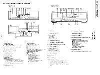
VOZL≥JM/OZLdM-01 1-1. LOCATION AND FUNCTION OF CONTROLS (TC-WR720) 8 .....„ ^ i,# FT- ,, - . -1EL.6=1.. el) :„- t 6 1 J .L.J • i-H1 E-- - Emii SONY 2 13 14 15 (TC-WR720A) i3 SONY -st 61 il8 9 W111 12 131 A • Ai i ..k_ l' F I E, Liu= fraj_c_p 1 18 16 I NO11103S o (11::, 1== OI - Sony TC-WR720A | Service Manual - Page 5
SECTION 2 DISASSEMBLY TC-WR720/WR720A Note: Follow the disassembly procedure in the numerical order given. 2-1. FRONT PANEL (WR720A) 0 Remove the connector from audio system control board. CN806 CN701 CN503 CN801 CN601 III CN505 CN501 CN802 CN804 CN502 0 front panel CN803 CN805 CN504 - Sony TC-WR720A | Service Manual - Page 6
TC-WR720/WR720A 2-3. FRONT PANEL (WR720) 0 Remove the connector from audio system control board. 0 Push the EJECT button. O BVTT3 X 6 0 cassette lid 0 BVTT3 x8 2-4. MECHANISM DECK (WR720) 0 mechanism deck CN701 if CN806 CN505 CN801 CN601 audio system control board front panel 0 BVTT2.6x 6 - Sony TC-WR720A | Service Manual - Page 7
2-5. CAPSTAN MOTOR, REEL MOTOR (1) 0 PTPWH2 X23 TC-WR720/WR720A 0 fitting base 4 rr 0 When installing, pull the FR belt and put arround claws. ( 1) 0 When installing, pull the capstan belt and put arround claws. 2-6. CAPSTAN MOTOR, - Sony TC-WR720A | Service Manual - Page 8
TC-WR720/WR720A SECTION 3 MECHANICAL ADJUSTMENTS PRECAUTION 1. Clean the following parts with a denatured alcohol- moistened swab : record/playback head pinch roller erase head rubber belts capstan idlers 2. Demagnetize - Sony TC-WR720A | Service Manual - Page 9
Record/Playback Head Azimuth Adjustment DECK A DECK B Procedure: 1. Reverse Playback Mode test tape P-4-A100 (10kHz, -10dB) 47k0 VTVM set LINE OUT 2. Turn the adjustment screw for the maximum output levels. If these levels do notmatch, turn the adjustment screw until both of output levels - Sony TC-WR720A | Service Manual - Page 10
Playback Level Adjustment Procedure: -Forward Playback Mode- test tape P-4-L300 (315kHz, 0dB) DECK A DECK B 47kO VTVM O set LINE OUT Adjust each RV11 (L-CH) and RV21 (R-CH) so that the VTVM reading becomes within adjustment limits below on both of deck A and deck B. Adjustment Limits : LINE - Sony TC-WR720A | Service Manual - Page 11
Adjustment Limits : 10kHz playback output relative to the 315Hz output : 0±0.5dB (0.732 to 0.82IV) Adjustment Location : audio system control board Record Level Adjustment DECK A DECK B Setting : REC LEVEL control: standard record position (Refer to page 8.) Procedure: 1. Record Mode AF OSC O- - Sony TC-WR720A | Service Manual - Page 12
B-29 D-29 D-30 B-28 C-26 C-28 C-26 G-20 H-30 H-29 H-29 E-28 F-27 F-25 H-27 H-28 G-26 G-27 G-25 D-17 D-16 D-16 D-13 1: Used on TC-WR720 only. 0 2: Used on TC-WR720A only. SW (A) board HP board SW (B) board HX-PRO board (B) SW-A board translation MD (C) board (DECK B) board (B) (DECK B) - Sony TC-WR720A | Service Manual - Page 13
- Sony TC-WR720A | Service Manual - Page 14
le numero speci number specified. fie. • I- 1: adjustment for repair. N • Voltage is de with respect to ground under no-signal R573 30L R574 43k 3_61 R575 56k 47 k R579 39k R584 5Ik R585 62k 51k R586 WR720 WR720A 43k 36k 36k 30k 22% 18k 43k 36k 50k 43k 27k 20k 62k 56k 394 36k MC14051 - Sony TC-WR720A | Service Manual - Page 15
12 82 XI 000,1 X0 X3 A iC806 -7 4 MC I 4052BCP DEC B 17 52 RB63 39k (WR720A) 2X0 2X2 2800N 2X3 2X1 'EH 4 13864 3.9k(WR72 9 lk (wR7200 6862{108 r',„11;3A18) or less unless otherwise • • :: internal component. adjustment for repair. • Voltage is dc with respect to ground under no-signal - Sony TC-WR720A | Service Manual - Page 16
5-6. SCHEMATIC DIAGRAM -PANEL SECTION- 1 I 2 I 3 I 4 I 5 6 7 8 A B C D E F G H J K Note: • All capacitors are in µF unless otherwise noted. pF: µµF 50WV or less are not indicated except for electrolytics and tantalums. • All resistors are in f2 and 14,V1I or less unless otherwise - Sony TC-WR720A | Service Manual - Page 17
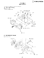
in the remark column. • Items marked "*" are not stocked since they are seldom required for routine service. Some delay should be anticipated when ordering these items. 6-1. CHASSIS SECTION 5 WR720A SECTION 6 EXPLODED VIEWS • Due to standardization, parts with part number suffix -XX and -X may be - Sony TC-WR720A | Service Manual - Page 18
6-2. FRONT PANEL SECTION (WR720A) 913 63 906 913 61 60 58 59 VT 55 70 907 A B 909 56 AA 55 65 912 (including A E, F) 55 55 0 not supplied A F 910 not - Sony TC-WR720A | Service Manual - Page 19
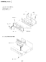
6-3. FRONT PANEL SECTION (WR720) 232 220 A D 212 not supplied 225213 9 226 2 4 223 913 901 (including A E -G) 233 907 rJ K 906 ( A B 227' 234 sri 228 915 (including A A -D) 913 909 235 236 208,N623 201- 221 FL901 2\17 ---- A B 211 S87 (DECK A) L 210 232,1 ____216 not - Sony TC-WR720A | Service Manual - Page 20
TC-WR720/WR720A 6-4. MECHANISM SECTION-1 (DECK A, B: TCM-19ORB12) 119 Ml 119 I 111 119 118 110 117 109 112 M2 not supplied 917 916 1'13 115 108 107 114 - Sony TC-WR720A | Service Manual - Page 21
TC-WR720/WR720A 6-5. MECHASISM SECTION-2 (DECK A, B: TCM-190RB12) 158 159 156 157 162 161 166 165 164 163 151 -" I 160 155 154 153 152 Ref.No Part No. - Sony TC-WR720A | Service Manual - Page 22
ELECTRICAL PARTS LIST TC-WR720/WR720A NOTE: • Due to standardization, replacements in the parts list may be different from the parts specified in the diagrams or the components used on the set. • Items marked "*" are not stocked since they are seldom required for routine service. Some delay should - Sony TC-WR720A | Service Manual - Page 23
TC-WR720/WR720A Ref.No Part No. Description C702 C703 C704 C705 C707 1-124 564-339-00 CN703 * 1-564-510-11 CN801 *1-568-830-11 CN802 *1-568-828-11 CN803 *1-568-828-11 (WR720A) PIN, CONNECTOR 5P PLUG, CONNECTOR 7P SOCKET, CONNECTOR IIP SOCKET, CONNECTOR 9P SOCKET, CONNECTOR 9P CN804 * 1-568-828- - Sony TC-WR720A | Service Manual - Page 24
-900-89 8-729-801-84 8-729-801-84 8-729-900-61 TRANSISTOR 2SD1761-EF TRANSISTOR DTC144ES TRANSISTOR 2SB1013-4 TRANSISTOR 2SB1013-4 TRANSISTOR DTA114ES TC-WR720/WR720A Ref.No Part No. Description Q804 Q805 Q806 Q807 Q851 8-729-900-80 TRANSISTOR 2SC3402-TP 8-729-900-61 TRANSISTOR DTA114ES 8-729 - Sony TC-WR720A | Service Manual - Page 25
TC-WR720/WR720A Ref.No Part No. Description R156 1-249-429-11 CARBON 10K R171 1-249-433-11 CARBON 22K R172 1-249-417-11 CARBON 1K R173 1-247-858-11 CARBON 13K R174 1-249-421-11 CARBON 2.2K R181 1-249-429-11 (WR720A). . .. CARBON 10K R181 1-249-433-11 (WR720). . .. CARBON 22K R182 - Sony TC-WR720A | Service Manual - Page 26
1/4W 5% 1/4W 5% 1/4W 5% 1/4W 5% 1/4W 5% 1/4W 5% 1/4W 5% 1/4W 5% 1/4W 5% 1/4W 5% 1/4W 5% 1/4W 5% 1/4W 5% 1/4W 5% 1/4W 5% 1/4W 5% 1/4W 5% 1/4W 5% 1/4W 5% 1/4W 5% 1/4W TC-WR720/WR720A Ref.No Part No. Description R709 R710 R711 R712 R713 1-249-426-11 CARBON 1-249-422-11 CARBON 1-249-430-11 CARBON - Sony TC-WR720A | Service Manual - Page 27
TC-WR720/WR720A Ref.No Part No. Description R908 1-249-415-11 (WR720A). . . . CARBON 680 R909 1-249-415-11 (WR720A). . . . CARBON 680 R910 1-249-415-11 (WR720A). . . . CARBON 680 R918 1-249-413-11 CARBON 470 R919 1-249-437-11 CARBON 47K 5% 1/4W 5% 1/4W 5% 1/4W 5% 1/4W 5% 1/4W R920 - Sony TC-WR720A | Service Manual - Page 28
01 CUSHION 3-703-450-01 (US). . . .INSTRUCTION *3-703-710-41 STICKER, SONY SYMBOL (12) 3-751-915-21 (WR720A). . . .MANUAL, INSTRUCTION (ENGLISH) 3-751-915-31 (Canadian, E). . . .MANUAL, INSTRUCTION (FRENCH) 3-751-921-11 (AEP). . . .MANUAL, INSTRUCTION (ENGLISH, FRENCH, SPANISH, PORTUGUESE) 3-751-921 - Sony TC-WR720A | Service Manual - Page 29
TC-WR720/WR720A 9-955-929-11 Sony Corporation Audio Group English 90F0477-1 Printed in Japan © 1990. 6 - Sony TC-WR720A | Service Manual - Page 30
TC-WR120/WR120A SONY.. SERVICE MANUAL SUPPLEMENT-1 File this supplement with the Service Manual. Subject : block diagram US Model Canadian Model E Model TC-WR720A AEP Model TC-WR720 9-955-929-81 Sony Corporation Audio Group English 90L0481-1 Printed in Japan 0 1990. 12 Published by Customer - Sony TC-WR720A | Service Manual - Page 31
TC-WR720/WR720A TC-WR720/WR720A TC-WR720/WR720A J301 -I LIN!E IN HRPE101(A) REC/PB HEAD L-CH DECK:A HRPE101(B) REC/PB HEAD DECK:B HRPE101(A) ERASE HEAD DECK:B HRPEI01(B) ERASE HEAD 32 . DECK:B RV501-1(WR720) RV902-I(WR720A) BALANCE 01/502-1(WR720) 00901-1(WR720A) REG LEVEL IC3I(A) PB ELI AMP - Sony TC-WR720A | Service Manual - Page 32
US Model Canadian Model E Model TC-WR720A AEP Model TC-WR720 CORRECTION-1 Correct your service manual as shown below. illir : indicates LINE OUT level : -5±0.5dB(0.411 to 0.462V) I 41 9-955-929-91 Sony Corporation Audio Group English 93J0487-1D Printed in Japan © 1993.10 Published by Audio
-
 1
1 -
 2
2 -
 3
3 -
 4
4 -
 5
5 -
 6
6 -
 7
7 -
8
-
9
-
10
-
11
-
12
-
13
-
14
-
15
-
16
-
17
-
18
-
19
-
20
-
21
-
22
-
23
-
24
-
25
-
26
-
27
-
28
-
29
-
30
-
31
-
32
 |
 |
SERVICE
MANUAL
0>
•
This
photo
is
TC-WR720.
US
Model
Canadian
Model
E
Model
TC-WR720A
AEP
Model
TC-WR720
SPECIFICATIONS
Recording
system
4
-track
2
-channel
stereo
Fast
winding
time
Approx.
90
sec.
(with
HF-60
cassette)
Bias
AC
bias
Signal-to-noise
ratio
(NAB,
at
peak
level)
Dolby
NR
switch
Cassette
OFF
B
-TYPE
ON
C
-TYPE
ON
Type
IV
(Sony
METAL
-ES)
58dB
66dB
73dB
Type
II
(Sony
UX-S)
57dB
65dB
72dB
Type
I
(Sony
HF-S)
55dB
(WR720)
54dB
(WR720A)
63dB
70dB
Total
harmonic
distortion
1.0%
(with
Sony
METAL
-ES
cassettes)
Frequency
response
(DOLBY
NR
OFF)
Type
IV
cassette
(Sony
METAL
-ES)
30-18,000Hz
(±3dB)
(WR720)
30-15,000Hz
(±3dB)
(WR720A)
30-14,000Hz
(OVU
recording)
(WR720)
30-13,000Hz
(OVU
recording)
(WR720A)
Type
II
cassette
(Sony
UX-S)
30-17,000Hz
(±3dB)
(WR720)
20-15,000Hz
(±3dB)
(WR720A)
Type
I
cassette
(Sony
HF-S)
30-15,000Hz
(±3dB)
(WR720)
30-14,000Hz
(±3dB)
(WR720A)
Wow
and
flutter
Inputs
Line
inputs
(phono
jacks)
Sensitivity
77.5mV
(-20dB)
Input
impedance
50kohms
0.07%
WRMS
(NAB)
El.
trM;),T.
Refe: f0 ne
arido
pa! c,D;.unler,ts
Model
Name
Using
Similar
Mechanism
TC-WR620
TCM-19ORBld
Tape
Transport
Mechanism
Type
Output
Line
outputs
(phono
jacks)
Rated
output
level
0.44V
(—5dB)
at
a
load
impedance
of
47kohms
Load
impedance
Over
10kohms
Headphones
(stereo
phono
jack)
Output
level
0.3mW
at
a
load
impedance
of
32
ohms
General
Power
requirements
Power
consumption
Dimensions
Weight
Supplied
accessories
120V
AC,
60Hz
(US,
Canadian
model)
220V
AC,
50/60Hz
(AEP
model)
120,
220,
240,
50/60Hz
(E
model)
33
watts
Approx.
430
X135
X
285mm
(w/h/d)
(17
X5
3
/
8
X11
1
/
4
inches)
including
projecting
parts
and
controls
Approx.
5kg
(11
lbs
1
oz)
(WR720)
Approx.
4.6kg
(10
lbs
3
oz)
(WR720A)
Audio
connecting
cord
(2)
Remote
commander
(RM-900W)
(E
model
only)
Conversion
adaptor
(E
model
only)
Design
and
specifications
subject
to
change
without
notice.
STEREO
CASSETTE
DECK
SONY