Sony XR-CA350X Installation/Connection Instructions
Sony XR-CA350X - Fm-am Cassette Car Stereo Manual
 |
View all Sony XR-CA350X manuals
Add to My Manuals
Save this manual to your list of manuals |
Sony XR-CA350X manual content summary:
- Sony XR-CA350X | Installation/Connection Instructions - Page 1
3-246-853-11 (2) FM/AM Cassette Car Stereo Installation/Connections Installation/Connexions 2 A B BUS AUDIO IN BUS CONTROL IN AUDIO OUT REAR XR-CA350X Sony Corporation © 2003 Printed in Malaysia 1 1 4 2 3 × 4 5 × 2 Equipment used in illustrations (not supplied) Appareils utilisés dans les - Sony XR-CA350X | Installation/Connection Instructions - Page 2
changer Fourni avec le changeur de CD/MD Source selector (not supplied) Sélecteur de source (non fourni) XA-C30 Supplied with XA-C30 Fourni avec le XA-C30 BUS AUDIO IN BUS CONTROL IN from car -in speaker wires installed in your car if the instructions. •Le support uniquement aux amplificateurs - Sony XR-CA350X | Installation/Connection Instructions - Page 3
to dashboard/center console vers le tableau de bord/la console centrale Bracket Support Bracket Support Existing parts supplied with your car Pièces existantes fournies avec la voiture 2 max. size 5 × 8 mm (7/32 × 11/32 in) Dimensions max. 5 × 8 mm (7/32 × 11/32 po) B NISSAN 2 max. size 5 × 8 mm - Sony XR-CA350X | Installation/Connection Instructions - Page 4
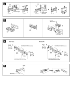
3 are properly engaged in the slots of the unit (5-3). Mounting the unit in a Japanese car (6) You may not be able to install this unit in some makes of Japanese cars. In such a case, consult your Sony dealer. Note To prevent malfunction, install only with the supplied screws 2. How to detach and
-
 1
1 -
 2
2 -
 3
3 -
 4
4
 |
 |
Sony Corporation
© 2003
Printed in Malaysia
XR-CA350X
3-246-853-
11
(2)
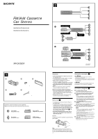
Equipment used in illustrations (not supplied)
Appareils utilisés dans les illustrations (non fournis)
Cautions
•This unit is designed for negative ground 12 V
DC operation only.
•Do not get the wires under a screw, or caught
in moving parts (e.g., seat railing).
•Before making connections, turn the car
ignition off to avoid short circuits.
•Connect the
yellow
and
red
power input leads
only after all other leads have been connected.
•
Run all ground wires to a common ground
point.
•Be sure to insulate any loose unconnected
wires with electrical tape for safety.
Notes on the power supply cord (yellow)
•When connecting this unit in combination with
other stereo components, the connected car
circuit’s rating must be higher than the sum of
each component’s fuse.
•When no car circuits are rated high enough,
connect the unit directly to the battery.
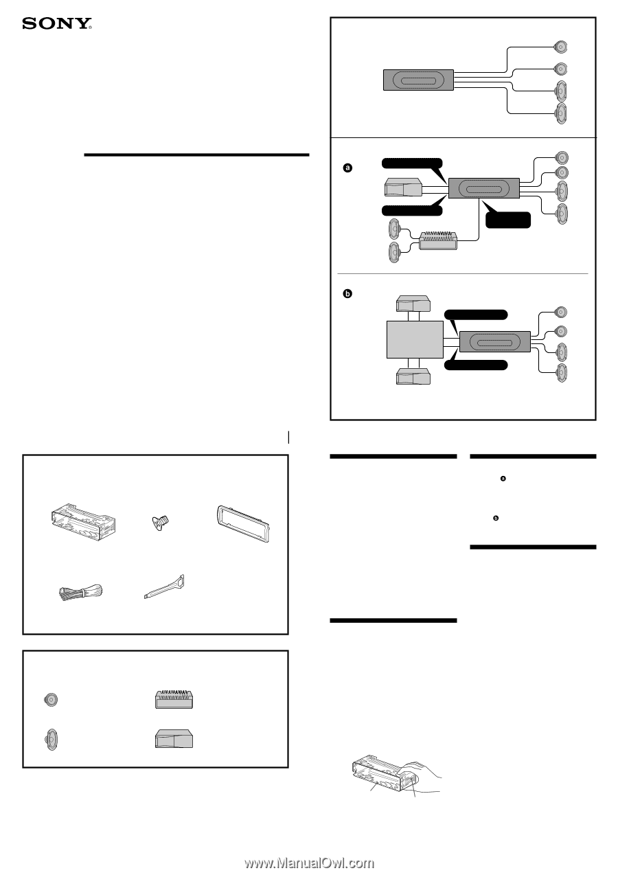
Parts Iist (
1
)
•The numbers in the list are keyed to those in
the instructions.
•The bracket
1
and the protection collar
3
are
attached to the unit before shipping. Before
mounting the unit, use the release keys
5
to
remove the bracket
1
and the protection collar
3
from the unit. For details, see “Removing
the protection collar and the bracket (
4
)” on
the reverse side of the sheet.
•
Keep the release keys
5
for future use as
they are also necessary if you remove the
unit from your car.
Caution
Handle the bracket
1
carefully to avoid injuring
your fingers.
Note
Before installing, make sure that the catches on
both sides of the bracket 1 are bent inwards 2 mm
(
3
/
32
in). If the catches are straight or bent outwards,
the unit will not be installed securely and may spring
out.
B
1
2
×
4
3
4
5
×
2
Power amplifier
Amplificateur de puissance
CD/MD changer
Changeur de CD/MD
Front speaker
Haut-parleur frontal
Rear speaker
Haut-parleur arrière
BUS AUDIO IN
BUS CONTROL IN
BUS CONTROL IN
BUS AUDIO IN
A
Installation/Connections
Installation/Connexions
FM
/
AM Cassette
Car Stereo
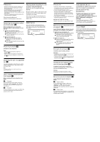
Connection example (
2
)
Notes
(
2
-B-
)
• Be sure to connect the ground cord before
connecting the amplifier.
• If you connect an optional power amplifier and do
not use the built-in amplifier, the beep sound will
be deactivated.
Tip
(
2
-B-
)
For connecting two or more CD/MD changers, the
source selector XA-C30 (optional) is necessary.
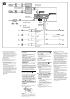
Connection diagram (
3
)
1
To a metal surface of the car
First connect the black ground lead, then
connect the yellow and red power input leads.
2
To the power antenna control lead or power
supply lead of antenna booster amplifier
Notes
• It is not necessary to connect this lead if there
is no power antenna or antenna booster, or
with a manually-operated telescopic antenna.
• When your car has a built-in FM/AM antenna in
the rear/side glass, see “Notes on the control
and power supply leads.”
3
To AMP REMOTE IN of an optional power
amplifier
This connection is only for amplifiers. Connecting
any other system may damage the unit.
4
To the +12 V power terminal which is energized
in the accessory position of the ignition key
switch
Notes
• If there is no accessory position, connect to the
+12 V power (battery) terminal which is
energized at all times.
Be sure to connect the black ground lead to a
metal surface of the car first.
• When your car has a built-in FM/AM antenna in
the rear/side glass, see “Notes on the control
and power supply leads.”
5
To the +12 V power terminal which is energized
at all times
Be sure to connect the black ground lead to a
metal surface of the car first.
*
not supplied
*
non fourni
Source selector
*
Sélecteur de source
*
XA-C30
AUDIO OUT
REAR
Catch
1
2
1