TASCAM DM-24 Installation and Use Owners Manual
TASCAM DM-24 Manual
 |
View all TASCAM DM-24 manuals
Add to My Manuals
Save this manual to your list of manuals |
TASCAM DM-24 manual content summary:
- TASCAM DM-24 | Installation and Use Owners Manual - Page 1
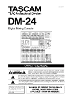
DM-24 Digital Mixing Console Professional OWNER'S MANUAL Ü CAUTION: TO REDUCE THE RISK OF ELECTRIC SHOCK, DO NOT REMOVE COVER (OR BACK). NO USER-SERVICEABLE PARTS INSIDE. REFER SERVICING TO QUALIFIED SERVICE operating and maintenance (servicing) instructions in the literature accompanying - TASCAM DM-24 | Installation and Use Owners Manual - Page 2
power point, then obtain an appropriate safety approved extension lead or consult your dealer. If nonetheless the mains plug is cut off, remove the fuse and dispose of the plug immediately, to avoid a possible shock hazard by inadvertent connection to the mains supply instruction manual TASCAM DM-24 - TASCAM DM-24 | Installation and Use Owners Manual - Page 3
: a) when the power-supply cord or plug is damaged. b) if liquid has been spilled, or objects have fallen into the product. c) if the product has been exposed to rain or water. d) if the product does not operate normally by following the operating instructions. Adjust only those controls that are - TASCAM DM-24 | Installation and Use Owners Manual - Page 4
Target link 23 Automation synchronization source 23 TC IN 23 MIDI IN MTC 24 INT 24 INT. START TIME 24 4 TASCAM DM-24 FLY WHEEL (frames 24 DIGITAL screens 24 CLOCK settings 24 High sampling frequency 25 Fs Status 25 D-IN MANUAL SETUP 25 WORD SYNC IN 25 TDIF interfaces 25 ADAT 25 AES3 - TASCAM DM-24 | Installation and Use Owners Manual - Page 5
Meter 51 EQ and buss assignments 51 Fader section 51 Mute and fader groups 51 Digital trim control 51 Pan control 51 Balance controls for stereo linked pair 52 Global pan 52 Ganging 52 Setup 52 Dynamics screen time 66 Gate decay time 66 Expander 66 Threshold 66 Ratio 66 TASCAM DM-24 5 - TASCAM DM-24 | Installation and Use Owners Manual - Page 6
To use a machine control mapping 83 Viewing the transport mappings 83 Editing a mapping 83 6 TASCAM DM-24 General parameters 83 Program Change channels 83 Program Change values 84 General MIDI parameters 84 MIDI OUT Active Sensing 84 OUTPUT MTC when slaved 84 RESET (ffh 84 MIDI filtering - TASCAM DM-24 | Installation and Use Owners Manual - Page 7
a buss pattern 108 Assigning modules 108 "Pan" controls 109 Global boom levels (5.1 only 110 15 - and delay 116 Libraries 116 Other screens 117 16 - Options Clock sources 118 Cascade card 119 Setting up the cascade 119 and troubleshooting 127 Block diagram (normal sampling TASCAM DM-24 7 - TASCAM DM-24 | Installation and Use Owners Manual - Page 8
automation system, allowing full real-time control of almost all mix parameters with no need for connection to other units • an optional meter bridge unit provides channel and master metering facilities through LED bargraph displays which are switchable in "layers" 8 TASCAM DM-24 Reference Manual - TASCAM DM-24 | Installation and Use Owners Manual - Page 9
power cord • A warranty card • A list of authorized TASCAM service stations About this manual Please note the following typographical and other conventions used in this manual: • Physical "push" controls of the DM-24 are referred to as "keys". • "Push" controls which are shown and used on the screen - TASCAM DM-24 | Installation and Use Owners Manual - Page 10
by the DM-24. You may use this to help you understand what is going on when you see a message displayed on the screen. Index : We try to make the index a useful place to look if you need help on a particular topic. Use the index first when searching for an answer. 10 TASCAM DM-24 Reference Manual - TASCAM DM-24 | Installation and Use Owners Manual - Page 11
high sampling frequencies, they output such a base frequency clock. If the external device does not do so, and only outputs a high sampling frequency clock, the DM-24 must be used as the word clock master for the system. TASCAM DM-24 Reference Manual 11 - TASCAM DM-24 | Installation and Use Owners Manual - Page 12
parameter for a number of channels or modules at once, and the "module" control screens controlling all the parameters for one module. Sometimes a key will have two labels. The you want to edit. The screen changes to show the settings for the selected module: 12 TASCAM DM-24 Reference Manual - TASCAM DM-24 | Installation and Use Owners Manual - Page 13
PODs The DM-24 features four rotary controls immediately below the screen, called PODs. These are used as "soft" controls to adjust parameters; that is, they have no fixed assignment to control any single POD or encoder changes values in "coarse" or accelerated mode. TASCAM DM-24 Reference Manual 13 - TASCAM DM-24 | Installation and Use Owners Manual - Page 14
control setting is memorized between screens (and even when the DM-24 is turned off and on again). It is therefore possible for the faders to move when the screen is changed. The layer continues flashing as long as the faders are not controlling the channel levels. 14 TASCAM DM-24 Reference Manual - TASCAM DM-24 | Installation and Use Owners Manual - Page 15
key (usually soft key 1) is used to bring up a small menu at the bottom of the screen: When such a menu pops up, either the dial or the POD corresponding to the soft key ( encoders) is lit, and the band controlled is determined by the appropriate EQUALIZER key. TASCAM DM-24 Reference Manual 15 - TASCAM DM-24 | Installation and Use Owners Manual - Page 16
accuracy, intermediate values are shown by two LEDs being lit simultaneously, as in the illustration below: = on = dimmed = off Encoders used as Q controls The Q of an EQ band refers to the width of the filter when it is in notch or peak mode (but not in shelf or 16 TASCAM DM-24 Reference Manual - TASCAM DM-24 | Installation and Use Owners Manual - Page 17
a wide portion of the spectrum, as shown below: = on = dimmed = off Encoders used as pan controls When the encoders are used to make pan settings, the center pan position is represented in the same way as a setting just below maximum (9.6 dB): = on = dimmed = off TASCAM DM-24 Reference Manual 17 - TASCAM DM-24 | Installation and Use Owners Manual - Page 18
are all colored purple for easy identification. These keys are the AUTOMATION block by the transport controls, and the purple key near the rotary encoders. There is a separate "shift" key to control the second function of some of the automation keys (and the 18 TASCAM DM-24 Reference Manual - TASCAM DM-24 | Installation and Use Owners Manual - Page 19
status As explained in the automation manual, the automation engine can be turned on or off in the main automation screen. When the automation engine is enabled, the word AUTO appears at the top of the screen, together with any automation mode currently enabled. TASCAM DM-24 Reference Manual 19 - TASCAM DM-24 | Installation and Use Owners Manual - Page 20
The DM-24 provides a number of options which control the overall functionality of the console. These are accessed through the OPTION and DIGITAL screens. Within these screens, you can (in the OPTION screen): • firstly, if either of the two "overload" options 20 TASCAM DM-24 Reference Manual - TASCAM DM-24 | Installation and Use Owners Manual - Page 21
the automatic linking of the selected channel to the selected meter layer. When this option is selected, if a channel is selected, the fader layer is changed, and then the fader layer is changed back again, the originally-selected channel is automatically selected. TASCAM DM-24 Reference Manual 21 - TASCAM DM-24 | Installation and Use Owners Manual - Page 22
screen controls will move to highlight the active band. SOLO The solo modes on the DM-24 can be set up in a number of different ways using this screen: FLASH Info. This on-screen should then contact your TASCAM dealer for service. Version Info. For service, etc. it is TASCAM DM-24 Reference Manual - TASCAM DM-24 | Installation and Use Owners Manual - Page 23
the source selected in the lower part of the screen to determine the automation synchronization source is displayed. top right of the display. NOTE A DTRS unit connected to the DM-24 through a card inserted in slot 1 or 2 cannot be used as a timecode DM-24 display. TASCAM DM-24 Reference Manual 23 - TASCAM DM-24 | Installation and Use Owners Manual - Page 24
the screen are filled, and show the slot cards currently fitted. The condition of a master clock status is shown using symbols. If the right clock is not available, or if the clock is out of the permissible limits, an appropriate symbol (cross or question mark) is shown. 24 TASCAM DM-24 Reference - TASCAM DM-24 | Installation and Use Owners Manual - Page 25
button, and press ENTER. A popup message appears. Use the ENTER key to continue with the check (cancel using any of the cursor keys). The DM-24 mutes, and a panel appears with details of all possible clock sources. Press ENTER once again to dismiss this panel. TASCAM DM-24 Reference Manual 25 - TASCAM DM-24 | Installation and Use Owners Manual - Page 26
be turned on or off individually using the on-screen Fs CONVERT buttons. The MUTE DEFEAT checkbox allows the DM-24 to ignore a status bit in some implementations of the stereo out as being either 24-bit data, 20-bit with noise shaping, or 16-bit with noise shaping. 26 TASCAM DM-24 Reference Manual - TASCAM DM-24 | Installation and Use Owners Manual - Page 27
optional interface cards that can be fitted to the DM-24 are automatically detected and the options can be set. These are described separately in "Options" on page 118. If slot cards have been fitted, they are shown on this screen, as in the example below. TASCAM DM-24 Reference Manual 27 - TASCAM DM-24 | Installation and Use Owners Manual - Page 28
a complete guide to the functions of the DM-24-treat it more as a "road-map" than a guidebook. Analog module inputs Other analog I/O Library section Module control Parameter control Monitoring Transport and automation control Module faders and selection, etc. 28 TASCAM DM-24 Reference Manual - TASCAM DM-24 | Installation and Use Owners Manual - Page 29
to be provided to the MIC channel inputs. These switches are arranged so that one switch controls the phantom power for four input channels (1 through 4, 5 through 8, 9 through 12, and 13 through convertor and the return (level -2dBu) is immediately before outputs. TASCAM DM-24 Reference Manual 29 - TASCAM DM-24 | Installation and Use Owners Manual - Page 30
explained in the automation guide. M Rotary encoders screen). O RECALL [UNDO/REDO] key The RECALL key is used to recall the settings of stored in the currently-select active library entry. It can also be used for comparison between the new and previous settings. 30 TASCAM DM-24 Reference Manual - TASCAM DM-24 | Installation and Use Owners Manual - Page 31
grouping (LINK/ GRP) 6 On-screen meters and fader Monitoring settings and positioning (METER/ options (MONITOR) FADER) 7 screen parameter values, etc. When the DM-24 is controlling the transport of a remote device, it may be used to perform a jog function. TASCAM DM-24 Reference Manual - TASCAM DM-24 | Installation and Use Owners Manual - Page 32
Meters These meters show the level of the currently-monitored signal. c SOLO control selected in the monitor screen to the monitor outputs control This control adjusts the level of the signal from the talkback microphone, fed to the selected outputs (slate or studio). 32 TASCAM DM-24 Reference Manual - TASCAM DM-24 | Installation and Use Owners Manual - Page 33
This key, with integral indi- cator, is used to "safe" any tracks of recording devices controlled by the DM-24. s SOLO key This key, with integral indicator, is used to enable the soloing function as depends on the device currently selected for external control. TASCAM DM-24 Reference Manual 33 - TASCAM DM-24 | Installation and Use Owners Manual - Page 34
. Rear panel The rear panel of the DM-24 houses the digital audio and control connections. 1 23 4 56 7 8 9 A B C NOTE Only use TASCAM-supplied and TASCAM-approved cables when making digital audio and control connections to the DM-24. Though the cables and connectors may resemble - TASCAM DM-24 | Installation and Use Owners Manual - Page 35
. Consult your TASCAM dealer for availability of such cards, and the documentation supplied with the cards for details of how to fit and use them. A POWER SWITCH and IN Use this push- on/push-off switch to switch the power to the DM24. Use only the provided power cord to connect the DM-24 to the AC - TASCAM DM-24 | Installation and Use Owners Manual - Page 36
able on the DM-24. These are referred to on-screen as M/L. They . Card slots Optional cards may be installed in the two card slots DM-24 has two internal digital effectors, with stereo returns. These returns are inputs and are assignable to channels 1 through 32. 36 TASCAM DM-24 Reference Manual - TASCAM DM-24 | Installation and Use Owners Manual - Page 37
cards. Six aux busses These six aux busses may be routed to the assignable sends, as well as to the internal effect units. Physical outputs This excludes the monitoring outputs (control be done in the fourth MODULE screen ("Channel source (CH SOURCE)" on page 58). TASCAM DM-24 Reference Manual 37 - TASCAM DM-24 | Installation and Use Owners Manual - Page 38
(CH17-32 IN) channels, respectively. 2 Press either of the two soft keys described above. These screens control the selection of the return block, the input source, and the Input sources Any mic/line input can vocal take with different compression or EQ settings. 38 TASCAM DM-24 Reference Manual - TASCAM DM-24 | Installation and Use Owners Manual - Page 39
that when slot cards are fitted, the number of the channel in the slot card may be offset by 8 or 16, so that channel 9 (or 17) of slot card 2 may be assigned to channel 1, etc. See "The FORMAT screen" on page accepted from one of these connectors at any one time. TASCAM DM-24 Reference Manual 39 - TASCAM DM-24 | Installation and Use Owners Manual - Page 40
the AUX 1-2 POD 4 button is highlighted, and when the cursor is on the ST module (bottom right of screen). The second such assignment (aux 1-2 to stereo) is possible only when the AUX 1-2 POD button is not the other assignment has been made, a popup message appears 40 TASCAM DM-24 Reference Manual - TASCAM DM-24 | Installation and Use Owners Manual - Page 41
17 through 32), the appropriate key is disabled. If either the MODULE or the ASSIGN screen is displayed, changes made to the assignments using these keys will be reflected in the display appear at the bottom of the screen, otherwise, a gray box will be shown. TASCAM DM-24 Reference Manual 41 - TASCAM DM-24 | Installation and Use Owners Manual - Page 42
any slot cards fitted. AUX5-6) or the control room signal (C.ROOM screen ("Digital output" on page 26). Move the cursor to the appropriate field (DIGITAL OUT1 or DIGITAL OUT2) on the left of the screen, Use the dial and ENTER key to select the desired output signal. 42 TASCAM DM-24 Reference Manual - TASCAM DM-24 | Installation and Use Owners Manual - Page 43
The assignable returns can be assigned to the inputs in the first and second I/O screens ("Assigning inputs to channels" on page 38). Press ENTER, and use the dial on-screen button (or using the ASSIGN PARAMETERS screen-"Other module parameters" on page 41). TASCAM DM-24 Reference Manual 43 - TASCAM DM-24 | Installation and Use Owners Manual - Page 44
controlling the phantom power supply to inputs 1-4, 5-8, 9-12, and 13-16. NOTE Always take care when switching the phantom power, to ensure that devices which may be damaged if phantom power is supplied are not connected to XLR connectors where phantom power is supplied. 44 TASCAM DM-24 Reference - TASCAM DM-24 | Installation and Use Owners Manual - Page 45
the 2TR IN terminals. These are assigned by default to the SEL 3 monitoring selection key for easy monitoring of the two-track master in the control room. Connect the two independent monitoring output sources (CR and STUDIO) to the appropriate monitoring systems. TASCAM DM-24 Reference Manual 45 - TASCAM DM-24 | Installation and Use Owners Manual - Page 46
and are all made on the rear panel of the unit. DTRS recorder connections WARNING Only use TASCAM-supplied and TASCAM-approved cables when making digital audio and control connections to the DM-24. Though the cables and connectors may resemble computer cables, they serve different purposes, and meet - TASCAM DM-24 | Installation and Use Owners Manual - Page 47
-24. Synchronization and control connections To clock slave From clock master P2-compatible equipment (e.g. VTR) OUT/THRU IN WORD SYNC RS-422 TIME CODE IN DM-24 TO METER MIDI THRU/ MTC OUT OUT IN External timecode source MIDI equipment MIDI equipment MU-24 TASCAM DM-24 Reference Manual - TASCAM DM-24 | Installation and Use Owners Manual - Page 48
of setting up the DM-24 to use the timecode. Consult the documentation with the meter unit for full details of installation and using the meters with the DM-24. See "Machine Control/Location" on page 80 for full details of control of other devices using the DM-24. 48 TASCAM DM-24 Reference Manual - TASCAM DM-24 | Installation and Use Owners Manual - Page 49
screen ("Select MODULE Return" on page 21). It is also possible to select the module for editing (when the MODULE screen (or the DYNAMICS screen) is displayed) by touching the module's fader, rather than pressing the SEL key ("Fader Auto MODULE Select" on page 21). TASCAM DM-24 Reference Manual - TASCAM DM-24 | Installation and Use Owners Manual - Page 50
key acts as a cursor here). Dynamics meter This meter shows the post-com- pressor effect of the dynamics processor assigned to the module. A graphical display of the settings is also provided (with attack, knee point, compression ratio, hysteresis, etc. displayed). 50 TASCAM DM-24 Reference Manual - TASCAM DM-24 | Installation and Use Owners Manual - Page 51
can be ganged to the module to the right (even-numbered channels can be linked to odd-numbered channels to the left). If this GANG control is enabled (move the cursor to it and press TASCAM DM-24 Reference Manual 51 - TASCAM DM-24 | Installation and Use Owners Manual - Page 52
is determined using POD 2: choose between ALL, EVEN (even-numbered channels), ODD (odd-numbered channels), 1-8, 9-16, 17-24 or 25-32. Press ENTER to apply the POD 1 setting and press ENTER again to confirm this when the popup appears (cancel with the cursor keys). 52 TASCAM DM-24 Reference Manual - TASCAM DM-24 | Installation and Use Owners Manual - Page 53
7 - Module operations-Dynamics screen Dynamics screen In this screen, the dynamics processor functions of the modules can be controlled. There are three different types of dynamics processor that can be details of the parameters are given in "Expander" on page 66. TASCAM DM-24 Reference Manual 53 - TASCAM DM-24 | Installation and Use Owners Manual - Page 54
27. When a band is set to non-notch filter or shelf mode, the Q cannot be set (the on-screen Q control is grayed-out) and all LEDs of the appropriate encoder are turned off. EQ band type The EQ band type the Q value, the narrower the band affected by the filter. 54 TASCAM DM-24 Reference Manual - TASCAM DM-24 | Installation and Use Owners Manual - Page 55
1 though 16 are being used as direct outputs. 1 With the SHIFT indicator off, press either AUX 1-2, AUX 3-4 or AUX 5-6, for control of the appropriate aux sends. The screen that appears depends on whether the selected aux sends have been linked together or not. TASCAM DM-24 Reference Manual 55 - TASCAM DM-24 | Installation and Use Owners Manual - Page 56
box highlighting four on-screen controls around the screen. Alternatively, press the SEL key for a given channel to jump the cursor to the appropriate position on the screen. The four controls correspond to the four and any input to the linked aux send is panned. 56 TASCAM DM-24 Reference Manual - TASCAM DM-24 | Installation and Use Owners Manual - Page 57
/POST for 3-4, 5-6) are made in the same way as for unlinked aux sends. made, the block diagram is updated to reflect these changes The above screen is the SETUP screen for channels 1 through 16. Channels 17 through 24, and 25 through TASCAM DM-24 Reference Manual 57 - TASCAM DM-24 | Installation and Use Owners Manual - Page 58
points (no return available) Channels 25 through 32 have no channel digital delay available. The controls available on these screens (through the PODs or through the cursor keys and data dial) are: Channel source ( milliseconds at 44.1k or 88.2k sampling frequencies. 58 TASCAM DM-24 Reference Manual - TASCAM DM-24 | Installation and Use Owners Manual - Page 59
channels share the same digital trim setting. Fader control At the top of the screen is a button which allows the faders to be 24 only. NOTE This is not a delay or echo effect as provided by the internal effectors. Linked channels share the same digital delay setting. TASCAM DM-24 Reference Manual - TASCAM DM-24 | Installation and Use Owners Manual - Page 60
Modules may be linked either by means of the linking screen (see the section on groups for details) or by control that exhibits this symptom. The change in the actual signal level of the second channel will be as smooth as the fader movement that you are making. 60 TASCAM DM-24 Reference Manual - TASCAM DM-24 | Installation and Use Owners Manual - Page 61
. Turning the control fully clockwise shows REVERSE on the screen. Mono switch (MONO SW) The mono switch is situated in the bottom row (POD 2). It allows the selection of either channel of the stereo pair (L MONO or R MONO), as well as the normal (STEREO) position. TASCAM DM-24 Reference Manual 61 - TASCAM DM-24 | Installation and Use Owners Manual - Page 62
the cursor to the on-screen COPY button and press ENTER. A confirmation popup message appears. 6 Press ENTER again to confirm the copy, or a cursor key to cancel. If neither of the checkboxes is checked when you press the COPY button, an error message is displayed. 62 TASCAM DM-24 Reference Manual - TASCAM DM-24 | Installation and Use Owners Manual - Page 63
entry is selected, the expander parameters will appear on screen. When the DYNAMICS screen is shown, to change from a gate to an expander, or vice versa, use the G/E... LIB soft key to bring up the library screen, and recall a library entry of the appropriate type. TASCAM DM-24 Reference Manual 63 - TASCAM DM-24 | Installation and Use Owners Manual - Page 64
" on page 99 for full details. No expander or gate is available for these master screens. Any on-screen controls associated with these processors are therefore unavailable. This includes the soft keys-only the compressor library is available from these screens. 64 TASCAM DM-24 Reference Manual - TASCAM DM-24 | Installation and Use Owners Manual - Page 65
are different from the channel 1-16 dynamics screens: No expander or gate available for these mas- ter screens. Any on-screen controls associated with these processors are therefore unavailable. This master counts as two channels, as shown in the sample screen here. TASCAM DM-24 Reference Manual 65 - TASCAM DM-24 | Installation and Use Owners Manual - Page 66
the signal is fed through the compressor, bargraph meters are shown on the appropriate scale: Gain reduction these have been assigned to the selected channel. Gate Threshold (THRESH), controlled by the POD 1 knob, allows the setting of the threshold at 0.2s apart. 66 TASCAM DM-24 Reference Manual - TASCAM DM-24 | Installation and Use Owners Manual - Page 67
all have the following parameters which may be set. The controls here refer to the controls on the DYNAMICS screen: Threshold (THRESH), controlled by the POD 1 knob, and variable from -48dB to Effective with brass (horn) sections, etc. Use with vocal lines TASCAM DM-24 Reference Manual 67 - TASCAM DM-24 | Installation and Use Owners Manual - Page 68
For the spoken word Comment General noise gate setting General noise agate setting An expander setting which is not too strong A slower expander setting 68 TASCAM DM-24 Reference Manual - TASCAM DM-24 | Installation and Use Owners Manual - Page 69
other fader groups, and mute groups can only be members of other mute groups. The grouping screen includes a linking sub-screen, and this is covered in "Linked modules" on page 60. If any channels have previously keys may be used as "no" or "escape" keys here. TASCAM DM-24 Reference Manual 69 - TASCAM DM-24 | Installation and Use Owners Manual - Page 70
message appears (Clear this mute grouping?), Turning groups on and off When a group is highlighted on screen (the cursor box surrounds it), either use the fourth soft key or the Copying mute settings to as a master and another group is currently selected, press- 70 TASCAM DM-24 Reference Manual - TASCAM DM-24 | Installation and Use Owners Manual - Page 71
, cursor keys for no). Turning groups on and off When a fader group is highlighted on screen (the cursor box surrounds it), either use the fourth soft key or Grouping layers It is the group to or from the layer controlled by the master group. The master group has TASCAM DM-24 Reference Manual 71 - TASCAM DM-24 | Installation and Use Owners Manual - Page 72
bullet mark added by its number when a subgroup is added (groups 6, 7 and 8 in the example screen). The tree diagram is updated. Pressing the SEL key corresponding to the master group brings up a popup the cursor keys may be used as "no" or "escape" keys here. 72 TASCAM DM-24 Reference Manual - TASCAM DM-24 | Installation and Use Owners Manual - Page 73
jack is determined in the channel IN screens of the I/O setup) and can therefore be used for monitoring the replay from the digital 2-track mastering device. The SEL 3 key is by default assigned to the analog 2- track inputs 9. These are typically used to monitor TASCAM DM-24 Reference Manual 73 - TASCAM DM-24 | Installation and Use Owners Manual - Page 74
DM-24. The setting of these keys may be changed using the MONITOR screen. With the SHIFT indicator lit, press the METER/ FADER [MONITOR] key to bring up this screen track inputs through the studio system when echoing the control room outputs to the studio (see below, " TASCAM DM-24 Reference Manual - TASCAM DM-24 | Installation and Use Owners Manual - Page 75
or busses (use the control room selection "Control room signal selection" on page 73 for this). The DM-24 provides two modes of soloing dB. happens is dependent on the settings made in the SOLO screen (from the OPTION display). MODE SELECT Either Mix Solo or Exclusive TASCAM DM-24 Reference Manual 75 - TASCAM DM-24 | Installation and Use Owners Manual - Page 76
channel is a group master, all Dimming and talkback On the same screen as the control room selection, it is possible to change the amount by which the control room outputs are "dimmed" (attenuated) when the dim is active working in the same way as the DIMMER key. If 76 TASCAM DM-24 Reference Manual - TASCAM DM-24 | Installation and Use Owners Manual - Page 77
, before any compressor insertion), PRE (pre-fader and post any compressor insertion), and POST (post fader). Since only 24 channels can be shown on screen at once, there is a choice of what will be metered on screen at any one time: either the 24 track returns, the TASCAM DM-24 Reference Manual 77 - TASCAM DM-24 | Installation and Use Owners Manual - Page 78
described as PRE (pre-fader), POST (post-fader) and INPUT (input)). Changes made here are reflected in the METER screen and vice versa. Use the SEL or cursor keys to move the box cursor around the screen in groups of 4 modules, and the PODs to set the fader values. 78 TASCAM DM-24 Reference Manual - TASCAM DM-24 | Installation and Use Owners Manual - Page 79
another value or changing the meter layer. These settings refer to both the on-screen meters and to the optional meter bridge meters. Note that when the meter layer is changed using the optional meter bridge, the STEREO master meter peak hold is not cleared. TASCAM DM-24 Reference Manual 79 - TASCAM DM-24 | Installation and Use Owners Manual - Page 80
software upgrade which contains the control capability for your device. Up to 16 devices may be added to the Machine Control List. If more devices are connected and added to the list than can be shown on screen, arrow marks appear at the top and bottom of the list. 80 TASCAM DM-24 Reference Manual - TASCAM DM-24 | Installation and Use Owners Manual - Page 81
a square box. Units whose CHASE mode cannot be remotely controlled have this item represented by two dashes (--). Use the cursor keys to navigate to the list item, and the ENTER key to toggle between on (a check mark is shown in the box) and off (the box is empty). TASCAM DM-24 Reference Manual 81 - TASCAM DM-24 | Installation and Use Owners Manual - Page 82
that may be controlled are detected and a new map is created for each such device. A message is shown if there are more devices connected than can be added to the list (that is, more than 10). If there are IDs associated with the devices, these are also shown. 82 TASCAM DM-24 Reference Manual - TASCAM DM-24 | Installation and Use Owners Manual - Page 83
key. Use the first soft key to bring up this screen: The DM-24's transport control keys will now control the device selected in that map and the other mapping features left of the screen, use the dial to select the MIDI channel (from 1 through 16), and press ENTER. TASCAM DM-24 Reference Manual 83 - TASCAM DM-24 | Installation and Use Owners Manual - Page 84
settings are made at the bottom left of the screen. The three libraries mentioned above (snapshot and the two RESET (ffh) This controls the action to be taken when a MIDI Reset message is received. The DM-24 can be either set to ignore all Reset requests, or when a Reset TASCAM DM-24 Reference Manual - TASCAM DM-24 | Installation and Use Owners Manual - Page 85
been selected in this option. NOTE Depending on the settings for frame display ("Edit Frames" on page 84), the frames value may or may not TASCAM DM-24 Reference Manual 85 - TASCAM DM-24 | Installation and Use Owners Manual - Page 86
memories. Editing one, and attempting to locate using ABS with a DTRS controller will almost certainly result in an unwanted result. It is suggested that 85), the controlled device will locate to the location memory point, minus the value set as the preroll time. 86 TASCAM DM-24 Reference Manual - TASCAM DM-24 | Installation and Use Owners Manual - Page 87
can MMC devices. Some devices controlled using the P2 protocol can accept these commands, but some cannot, depending on the manufacturer's implementation of the protocol. The list of devices which are assigned to the DM-24 for control is set up in the following way: TASCAM DM-24 Reference Manual 87 - TASCAM DM-24 | Installation and Use Owners Manual - Page 88
different pages of the devices selected for external control in the main EXTERNAL CONTROL setup screen. DTRS devices Depending on the functionality of the DTRS unit (DA-98HR, DA-78HR, DA-98, DA-88 or DA-38), 88 TASCAM DM-24 Reference Manual different options, such as track delay, dither setting - TASCAM DM-24 | Installation and Use Owners Manual - Page 89
Remember that all chains of DTRS units should be terminated. DA-98HR This screen (accessed using soft keys 3 and 4) allows the remote control of the following parameters. NOTE When the DA-98HR is set to any pair to be used as the clock source can then be chosen. TASCAM DM-24 Reference Manual 89 - TASCAM DM-24 | Installation and Use Owners Manual - Page 90
control the DTRS mixer when this screen is active (modules 1 through 8 control the first unit, and 9 through 16 control the second unit). While this is screen active, and the master layer is selected, the MASTER indicator flashes, as do the MUTE keys of the modules. 90 TASCAM DM-24 Reference Manual - TASCAM DM-24 | Installation and Use Owners Manual - Page 91
the screen. Use the cursor to navigate to the input (IN) or the tape (TP) row, and use the dial to make the assignments between tape and inputs. The input monitor can be switched on a track-bytrack basis. The three clock sources available are internal, word and video. TASCAM DM-24 Reference Manual - TASCAM DM-24 | Installation and Use Owners Manual - Page 92
Control on the screen here: Similar card is fitted in the DA-88, the timecode settings can be made in the same way as for the DA98 timecode. Punch preroll time only can be set (postroll cannot be set). Clock source options are restricted to internal, video and word. 92 TASCAM DM-24 Reference Manual - TASCAM DM-24 | Installation and Use Owners Manual - Page 93
Change number can be selected and set in this screen. As the example here shows, this may be used most often with MIDI volume (Control Change 7) in order to provide an easy way of independently controlling the volume of up to 16 MIDI devices connected to the DM-24. TASCAM DM-24 Reference Manual 93 - TASCAM DM-24 | Installation and Use Owners Manual - Page 94
Control 85 - 90 Undefined 91 Effect 1 Depth 92 Effect 2 Tremolo 93 Effect 3 Chorus 94 Effect 4 Detune 95 Effect 5 Phaser 96 Data increment 97 Data decrement 98 Non-Registered LSB 99 Non-Registered MSB 100 Registered LSB 101 Registered MSB 102 - 119 Undefined 94 TASCAM DM-24 - TASCAM DM-24 | Installation and Use Owners Manual - Page 95
has been selected, move the cursor to the on-screen BULK DUMP button, and press ENTER. In the section on Machine Control, it is also explained how the DM-24 can be set up to use or ignore certain MIDI dump process can be halted by pressing any of the cursor keys. TASCAM DM-24 Reference Manual 95 - TASCAM DM-24 | Installation and Use Owners Manual - Page 96
be used to mute and un-mute channels precisely in sync with the musical timing of a piece, rather than by timecode values. The Control Change messages transmitted in this way can also be used to make settings on remote MIDI devices in time with fader movements, etc. 96 TASCAM DM-24 Reference Manual - TASCAM DM-24 | Installation and Use Owners Manual - Page 97
and from the DM-24 To access this facility, use the CTRL. CHANGE (Control Change) screen of the MIDI/MC group, with the fourth soft key providing access to this screen: If two STEREO fader value. Assign MIDI channels and Control Change numbers to these parameters. TASCAM DM-24 Reference Manual 97 - TASCAM DM-24 | Installation and Use Owners Manual - Page 98
Notes OFF Active Sense Reset 1-16 1-16 x Control Change on the MIDI screen *b.Usable with the MIDI Controllers display *c: Usable with the MIDI Faders display MODE 1: OMNI ON, POLY MODE 3: OMNI OFF, POLY MODE 2: OMNI ON, MONO MODE 4: OMNI OFF, MONO O:Yes x: No 98 TASCAM DM-24 Reference Manual - TASCAM DM-24 | Installation and Use Owners Manual - Page 99
error message appears. 1 Use the + and - keys to the left of the display to change the library entry number shown at the top of the screen. 2 Press the STORE key below the + and - keys to store the current settings to the library. TASCAM DM-24 Reference Manual 99 - TASCAM DM-24 | Installation and Use Owners Manual - Page 100
that this may be a problem. the library that is to store the data, and press ENTER. The screen changes depending on the selected library, as a "preview" of the selected entry is shown, and the way in which this preview is displayed changes according to the library. 100 TASCAM DM-24 Reference Manual - TASCAM DM-24 | Installation and Use Owners Manual - Page 101
available when an entry is first stored, or when the EDIT soft key (3) is pressed from the library screen. Library entries may have a name consisting of up to 16 characters. Use POD 4 to scroll through the CANCEL soft key (3) to cancel the name editing operation. TASCAM DM-24 Reference Manual 101 - TASCAM DM-24 | Installation and Use Owners Manual - Page 102
"neutral" setting. All faders are set to nominal levels, and pan controls are set to center, etc. Specifically Item Value EQ switch ON EQ stored in a snapshot. As the list on the right of the screen is scrolled using POD 4, the snapshot image on the right changes TASCAM DM-24 Reference Manual - TASCAM DM-24 | Installation and Use Owners Manual - Page 103
Assign Snapshot name INITIAL-DATA Libraries-effects When the internal effect library is selected, the screen display changes as shown below: This differs from the other libraries, because it is possible the name. This type is automatically entered when the TASCAM DM-24 Reference Manual 103 - TASCAM DM-24 | Installation and Use Owners Manual - Page 104
which they have been designed. However, this is only a guide, and you should experiment with these set- Number Title 000 Snare the parameters for these dynamics processors vary, and accordingly the screen display of the current settings and the library entries reflect TASCAM DM-24 Reference Manual - TASCAM DM-24 | Installation and Use Owners Manual - Page 105
, peaking, notch or LPF or HPF filter. Storing, editing and naming, and recall operations are all as described in "Managing library entries" on page 99. TASCAM DM-24 Reference Manual 105 - TASCAM DM-24 | Installation and Use Owners Manual - Page 106
setting-starting point for experimentation For "pad" sounds to match vocals Vocal EQ starting points Elimination of AC (mains) noise "Squawk-box" vocal setting 106 TASCAM DM-24 Reference Manual - TASCAM DM-24 | Installation and Use Owners Manual - Page 107
"surround pan" controls. For monitoring, card (IFAN/DM). This allows easy connection of an analog multi-channel monitoring system to the DM-24. The assignment of the busses to the channels is shown by a number beside the representation of the on-screen speakers. TASCAM DM-24 Reference Manual - TASCAM DM-24 | Installation and Use Owners Manual - Page 108
. Assigning modules When a surround mode has been selected, the ASSIGN BUSS screen changes so that the usual buss assignments are not shown, but the modules are now assignable to the surround channels: The screen below shows the 2+2 surround assignment settings 108 TASCAM DM-24 Reference Manual - TASCAM DM-24 | Installation and Use Owners Manual - Page 109
/BAL - SURROUND key. Instead of a global screen showing all modules, the surround screen for the currentlyselected module and one other module is shown. If a pair of modules has been linked as a stereo pair, the stereo linking does not apply to the surround set- TASCAM DM-24 Reference Manual 109 - TASCAM DM-24 | Installation and Use Owners Manual - Page 110
also the "bar-graphs" (not meters) by each onscreen speaker, which to these positioning controls, in the 5.1 surround mode the screen. 2 Use POD 2 to change the selection group between ALL (all channels), ODD (odd-numbered channels), EVEN (even-numbered chan- 110 TASCAM DM-24 Reference Manual - TASCAM DM-24 | Installation and Use Owners Manual - Page 111
PODs to trim the individual channel levels as desired. It is also possible to use the faders to control the boom level (use the BOOM LEVEL FADER CONTROL button at the top of the screen, and the faders as described in "Using the faders to change values" on page 14. TASCAM DM-24 Reference Manual 111 - TASCAM DM-24 | Installation and Use Owners Manual - Page 112
, many of the control screens change as explained in this section. The word sync output from the DM-24 can be set to DM-24 itself can only accept normal-speed word sync when it is in high sampling frequency mode. The SLOT screen of the DIGITAL display shows this: 112 TASCAM DM-24 Reference Manual - TASCAM DM-24 | Installation and Use Owners Manual - Page 113
of AES/EBU channels available on any installed slot cards is now halved. The number of onboard compressors and dynamics processors, etc. is also reduced. However, the functionality of the components that make up the modules (EQ, etc.) is not impaired or reduced. TASCAM DM-24 Reference Manual 113 - TASCAM DM-24 | Installation and Use Owners Manual - Page 114
accept signals from the mic/line inputs) is shown here: Finally, the screen in which the assignable sends are used in high frequency sampling mode differs slightly other respects, this screen operates in the same way as its normal sampling frequency counterpart. 114 TASCAM DM-24 Reference Manual - TASCAM DM-24 | Installation and Use Owners Manual - Page 115
key has no effect. When either AUX 1-2 or AUX 3-4 is pressed, only sixteen channels are shown on screen. As can be seen here, there are only 16 channels available, and four aux sends. Links are made and unmade in the same way as in normal sampling frequency mode. TASCAM DM-24 Reference Manual 115 - TASCAM DM-24 | Installation and Use Owners Manual - Page 116
sampling) or Ns (normal sampling) beside their names in the list of library entries on the library screen. Also, note that the range for delay times remains the same, even though the sampling frequency is frequency mode, and recall them for use in the other mode. 116 TASCAM DM-24 Reference Manual - TASCAM DM-24 | Installation and Use Owners Manual - Page 117
in high sampling frequency mode, all screens which refer to the aux channels (such as the one below) reflect this. For example, in this screen, the meter layer cannot follow channels 17 through 32 (they do not exist) and therefore the option is not available. TASCAM DM-24 Reference Manual 117 - TASCAM DM-24 | Installation and Use Owners Manual - Page 118
fitted. In the case of the AES/EBU card, any of the four inputs (two in the case of high sampling frequency) can be selected as the word sync source. Cascade slaves automatically take their clock from the master (which is free to take it from any other source). 118 TASCAM DM-24 Reference Manual - TASCAM DM-24 | Installation and Use Owners Manual - Page 119
etc. to be controlled from the master unit, and thereby be shared between the two cascaded units, the two DM-24s can be used as one large digital console. The ENABLE checkboxes allow the selection from the master unit of which busses and functions will be shared. TASCAM DM-24 Reference Manual 119 - TASCAM DM-24 | Installation and Use Owners Manual - Page 120
of MIDI controllers can be assigned and used when using two DM-24 units cascaded together. NOTE Only the "local" effects can be used with inserts and assignable inserts on each unit. See the separate effects documentation for further details of assigning effects. 120 TASCAM DM-24 Reference Manual - TASCAM DM-24 | Installation and Use Owners Manual - Page 121
) are determined by the ADAT device, and may not be set on this screen. NOTE This card cannot be used in high sampling frequency mode. A message is displayed in the appropriate part of the screen if the card is fitted and high sampling frequency mode is selected. TASCAM DM-24 Reference Manual 121 - TASCAM DM-24 | Installation and Use Owners Manual - Page 122
inputs to channels" on page 38) and the outputs of the cards may be selected as either buss or aux send destinations ("Output assignments The word length can be set to be 24 or 20 bits long. The on-screen DETAIL button provides information on the signal currently . 122 TASCAM DM-24 Reference Manual - TASCAM DM-24 | Installation and Use Owners Manual - Page 123
output in this mode. AD/DA card This card provides eight balanced channels of analog input and eight balanced channels of analog output, converted at up to 24-bit resolution (the resolution is displayed from a connected MTR is locked, the LOCK indicator lights. TASCAM DM-24 Reference Manual 123 - TASCAM DM-24 | Installation and Use Owners Manual - Page 124
technical information about the DM-24. Analog audio I/O All specifications are given with the factory reference level of -16dBFS max) to -2dBu (TRIM min)) Input impedance 2.2kΩ +48V phantom power. Switchable in blocks of 4 channels (1-4, 5-8, 9-12, 13-16) 124 TASCAM DM-24 Reference Manual - TASCAM DM-24 | Installation and Use Owners Manual - Page 125
/DM 9-pin female D-sub connector (non-metric lock screws) wired to RS-422 standards 9-pin female D-sub connector (non-metric lock screws) wired for GPI control Pin 1=GPI1, Pin 2=GPI2, Pin 3=GPI3, Pin 4=GPI4, Pin 5=GPI5, Pin 6=GPI6, Pin 7=GPI7, Pin 8=GPI8, Pin 9=ground TASCAM DM-24 Reference Manual - TASCAM DM-24 | Installation and Use Owners Manual - Page 126
Backlit 320 x 240 LCD with contrast control 2 x 12-segment LED meters 17 x 100mm stroke, motor-driven touch-sensitive faders 582 x 657 x 198 (mm) 22.9 x 25.9 x 7.8 (in) 20.5kg (45.1lbs) 120VAC, 60Hz 230VAC, 50Hz 240VAC, 50Hz 82 W 8A E4 Power cord, warranty card 126 TASCAM DM-24 Reference Manual - TASCAM DM-24 | Installation and Use Owners Manual - Page 127
to the DM-24" on page 96). The DM-24 should be rebooted. Turn down the volume of all other devices and press ENTER. Shown if the data type being loaded by MIDI Bulk Dump transfer does not match the expected type ("Bulk transfer of data to the DM-24" on page 96). TASCAM DM-24 Reference Manual 127 - TASCAM DM-24 | Installation and Use Owners Manual - Page 128
- Specifications-Messages and troubleshooting Action Message Explanation ✖ cannot be used for control ("Serial output" on page 84). ✖ Can't Load MIDI Sys Ex data. SysEx filter is set in MIDI/MC [SETUP] screen] Press ENTER to continue " on page 99). 128 TASCAM DM-24 Reference Manual - TASCAM DM-24 | Installation and Use Owners Manual - Page 129
there is a problem overwriting a protected Cascade card" on page 119). Shown when a global screen has screen CLEAR button has been pressed to clear all mute groups ("Grouping" on page 69). Shown in automation, when the current data is to be cleared (using soft key 2) TASCAM DM-24 Reference Manual - TASCAM DM-24 | Installation and Use Owners Manual - Page 130
the DM-24" on page 96). Shown when requesting the deletion of an automation memory bank. Shown if a device has been selected in the Machine Control List ("Selecting devices for control" on page 80), but is not switched on or connected or is otherwise unavailable. 130 TASCAM DM-24 Reference Manual - TASCAM DM-24 | Installation and Use Owners Manual - Page 131
the on-screen LINK button has been pressed to link mute and fader groups ("Grouping" on page 69). The high sampling frequency mode is not supported (by another device in the system of which the DM-24 is aware). Reset the DM-24 to normal sampling frequency mode. TASCAM DM-24 Reference Manual 131 - TASCAM DM-24 | Installation and Use Owners Manual - Page 132
shown just before the mute operation ("High sampling frequency" on page 25). An attempt is made to assign a return from a non-existent slot card ("Card slots" on page 36). Popup message shown when cascade slave unit cannot be located ("Cascade card" on page 119). 132 TASCAM DM-24 Reference Manual - TASCAM DM-24 | Installation and Use Owners Manual - Page 133
17 - Specifications-Messages and troubleshooting Action Message ✔ OK to data ("Library functions" on page 99). Shown when the transport control mapping is to be overwritten ("Machine Control mapping memories" on page 82). Shown when assigning a link on page 69). TASCAM DM-24 Reference Manual 133 - TASCAM DM-24 | Installation and Use Owners Manual - Page 134
-Messages and troubleshooting Action Message 24). Sample information about the data transmitted from a digital output ("CLOCK settings" on page 24). Sample popup information screen for SPDIF data transmitted from a DIGITAL OUT ("CLOCK settings" on page 24). 134 TASCAM DM-24 Reference Manual - TASCAM DM-24 | Installation and Use Owners Manual - Page 135
troubleshooting Signal Info: Slot1 AES3 Card input 1 Format: AES/ 24). Sample popup information (details of a TDIF connection)-"CLOCK settings" on page 24. The screen given when the clock signal from the source selected is not present ("CLOCK settings" on page 24). TASCAM DM-24 Reference Manual - TASCAM DM-24 | Installation and Use Owners Manual - Page 136
select a new clock source, which is out of range ("CLOCK settings" on page 24). The DM-24 cannot recognize the card fitted in the optional slot. Check the card and its installation in the DM-24. Contact your TASCAM dealer for assistance if necessary. An attempt is being made to overwrite a read-only - TASCAM DM-24 | Installation and Use Owners Manual - Page 137
- Specifications-Messages and troubleshooting Action Message ✔ There 00 Antares : 1.00 TASCAM: 1.00 Press ENTER to continue. Explanation Shown when an attempt is made to copy parameters in the UTILITY PARAM. COPY screen ("UTILITY copying" on page page 22). TASCAM DM-24 Reference Manual 137 - TASCAM DM-24 | Installation and Use Owners Manual - Page 138
Specifications-Block diagram (normal sampling frequency) Block diagram (normal sampling frequency) 138 TASCAM DM-24 Reference Manual Analog INPUT 1-16 +48V MIC -56dBu to -2dBu LINE -42dBu to +12dBu INST -2dBu OL to METER [MTR] A/D TRIM RTN SEL 1-8 TDIF + SLOT[OPTION] TDIF/SLOT TDIF SLOT GRP - TASCAM DM-24 | Installation and Use Owners Manual - Page 139
17 - Specifications-Block diagram (high sampling frequency) Block diagram (high sampling frequency) TASCAM DM-24 Reference Manual 139 Analog INPUT 1-8 +48V MIC -56dBu to -2dBu LINE -42dBu to +12dBu INST -2dBu OL to METER [MTR] A/D TRIM RTN SEL 1-4 TDIF + SLOT[OPTION] TDIF/SLOT TDIF SLOT GRP/ - TASCAM DM-24 | Installation and Use Owners Manual - Page 140
17 - Specifications-Level diagram Level diagram 140 TASCAM DM-24 Reference Manual +20 (dBV) +10 0 (dBu) +20 LINE +12dBu +10 MIC 0 -2dBu MIC/LINE IN 1-16 (H.ROOM 16dB) ( -13.3dBu -30 (dBu) (dBV) +20 +20 +10 +10 0 0 -10dBV -10 -10 STUDIO OUTPUT -20 -20 TASCAM DM-24 Level Diagram Ver 1.07 - TASCAM DM-24 | Installation and Use Owners Manual - Page 141
volume control 32 cueing mode 85 cursor follows EQ Band Key (preference) 22 cursor keys 31 D DA-38 92 DA-78HR 90 DA-78HR mixer 90 DA-88 92 DA-98 91 DA-98HR 89 DA-98HR mixer 90 dial 31 digital audio I/O 125 digital connections 46 digital delay time 58 TASCAM DM-24 - TASCAM DM-24 | Installation and Use Owners Manual - Page 142
79 fader position 51, 79 fader sensitivity 21 fader setup 79 Fader->Meter Follow (option) 22 faders as controls 14 changing values with the faders 14 in snapshot 00 102 in surround 59 global pan 52 global screens 12 GPI 35 grouping 69, 102, 116 grouping layers 69, 71, 72 Index - 142 TASCAM DM-24 - TASCAM DM-24 | Installation and Use Owners Manual - Page 143
control 80 merge 35 MTC 35 Program Change 83 RESET (ffh) 84 settings 31 software updates 96 terminals IN, OUT and THRU 35 timecode 24, 80, 81, 84, 84 MIDI IN MTC 24 MODE SELECT (solo) 22, 75 MODULE key 30 module operations 49 module parameters 41 module screens 12 monitor outputs 29 TASCAM DM-24 - TASCAM DM-24 | Installation and Use Owners Manual - Page 144
20, 33 OPTION screen 20 oscillator 77 power switch 35 pptions 118 pre/post settings 56 preferences 21 preset library entries 67 compressors 104 EQ 106 gates 105 Program Change channels 83 Program Change values 84 punch keys and indicators 33 Index - 144 TASCAM DM-24 R repeat play (machine control - TASCAM DM-24 | Installation and Use Owners Manual - Page 145
control 32 TC generator 89 TC IN 23 TC REC 89 TDIF 25, 26, 35, 36, 37, 42, 46, 118, 121 card 121 connectors 37 interfaces 25 timecode 23, 24, 35, 48, 48, 82 display 20 flywheel 24 flywheel (frames) 24 generator 24 26 phase 25 setup 24 slave 11 sources 11, 89 varispeed 26 TASCAM DM-24 Index - 145 - TASCAM DM-24 | Installation and Use Owners Manual - Page 146
» DM-24 TEAC CORPORATION Phone: (0422) 52-5082 3-7-3, Nakacho, Musashino-shi, Tokyo 180-8550, Japan TEAC AMERICA, INC. Phone: (323) 726-0303 7733 Telegraph Road, Montebello, California
-
 1
1 -
 2
2 -
 3
3 -
 4
4 -
 5
5 -
 6
6 -
 7
7 -
8
-
9
-
10
-
11
-
12
-
13
-
14
-
15
-
16
-
17
-
18
-
19
-
20
-
21
-
22
-
23
-
24
-
25
-
26
-
27
-
28
-
29
-
30
-
31
-
32
-
33
-
34
-
35
-
36
-
37
-
38
-
39
-
40
-
41
-
42
-
43
-
44
-
45
-
46
-
47
-
48
-
49
-
50
-
51
-
52
-
53
-
54
-
55
-
56
-
57
-
58
-
59
-
60
-
61
-
62
-
63
-
64
-
65
-
66
-
67
-
68
-
69
-
70
-
71
-
72
-
73
-
74
-
75
-
76
-
77
-
78
-
79
-
80
-
81
-
82
-
83
-
84
-
85
-
86
-
87
-
88
-
89
-
90
-
91
-
92
-
93
-
94
-
95
-
96
-
97
-
98
-
99
-
100
-
101
-
102
-
103
-
104
-
105
-
106
-
107
-
108
-
109
-
110
-
111
-
112
-
113
-
114
-
115
-
116
-
117
-
118
-
119
-
120
-
121
-
122
-
123
-
124
-
125
-
126
-
127
-
128
-
129
-
130
-
131
-
132
-
133
-
134
-
135
-
136
-
137
-
138
-
139
-
140
-
141
-
142
-
143
-
144
-
145
-
146
 |
 |

DM-24
Digital Mixing Console
Professional
OWNER’S MANUAL
CAUTION: TO REDUCE THE RISK OF ELECTRIC SHOCK, DO NOT
REMOVE COVER (OR BACK). NO USER-SERVICEABLE PARTS INSIDE.
REFER SERVICING TO QUALIFIED SERVICE PERSONNEL.
The exclamation point within an equilateral triangle is intended to alert the user to the pres-
ence of important operating and maintenance (servicing) instructions in the literature
accompanying the appliance.
The lightning flash with arrowhead symbol, within an equilateral triangle, is intended to alert
the user to the presence of uninsulated “dangerous voltage” within the product’s enclosure
that may be of sufficient magnitude to constitute a risk of electric shock to persons.
This appliance has a serial number
located on the rear panel. Please record
the model number and serial number
and retain them for your records.
Model number
Serial number
Ü
ÿ
Ÿ
WARNING: TO PREVENT FIRE OR SHOCK
HAZARD, DO NOT EXPOSE THIS
APPLIANCE TO RAIN OR MOISTURE.
9101439701