TP-Link T2500G-10MPS T2500G-10MPSUN V1 Installation Guide
TP-Link T2500G-10MPS Manual
 |
View all TP-Link T2500G-10MPS manuals
Add to My Manuals
Save this manual to your list of manuals |
TP-Link T2500G-10MPS manual content summary:
- TP-Link T2500G-10MPS | T2500G-10MPSUN V1 Installation Guide - Page 1
Business Networking Solution Installation Guide JetStream Gigabit L2 Managed Switch T2500G-10MPS T2500G-10TS (TL-SG3210) - TP-Link T2500G-10MPS | T2500G-10MPSUN V1 Installation Guide - Page 2
- TP-Link T2500G-10MPS | T2500G-10MPSUN V1 Installation Guide - Page 3
A Troubleshooting. Appendix B Hardware Specifications. Audience Conventions This Installation Guide is for: Network Engineer Network Administrator ■■ Some models featured in this guide may be unavailable in your country or region. For local sales information, visit http://www.tp-link.com - TP-Link T2500G-10MPS | T2500G-10MPSUN V1 Installation Guide - Page 4
4.3 Console Port 16 4.4 Verify Installation 17 4.5 Power On 18 4.6 Initialization 18 Chapter 5 Configuration----------- 19 5.1 Configure the Switch via GUI 19 5.2 Configure the Switch Using CLI 20 Appendix A Troubleshooting--------- 23 Appendix B Hardware Specifications------ 25 II Contents - TP-Link T2500G-10MPS | T2500G-10MPSUN V1 Installation Guide - Page 5
bring abundant management policies. TP-Link JetStream Gigabit L2 Managed Switch integrates multiple functions with excellent performance, and is friendly to manage, which can fully meet the need of the users demanding higher networking performance. T2500G-10MPS L2 Managed PoE+ Switch is also a Power - TP-Link T2500G-10MPS | T2500G-10MPSUN V1 Installation Guide - Page 6
switch works properly On/Off The switch works improperly A 1000Mbps device is linked to the corresponding Green port, but no activity On A 10/100Mbps device is linked install the SFP module. T2500G-10TS features 2 individual SFP ports and supports 1000M SFP module connection only. 02 Introduction - TP-Link T2500G-10MPS | T2500G-10MPSUN V1 Installation Guide - Page 7
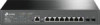
is shown as the following figure. Figure 1-2 Front Panel of T2500G-10MPS LEDs LED Mode Switch Button Console Port (RJ-45) Console Port (USB) 10/100/1000Mbps RJ45 Port SFP Port LEDs T2500G-10MPS has an LED mode switch button which is for switching the LED status indication. When the Speed LED is on - TP-Link T2500G-10MPS | T2500G-10MPSUN V1 Installation Guide - Page 8
Flashing On/Off Green Yellow Off On Flashing Off Green On Flashing Indication The switch is powered on The switch is powered off or power supply is abnormal Power supply is abnormal The switch works properly The switch works improperly All the fans work properly Not all the fans work properly - TP-Link T2500G-10MPS | T2500G-10MPSUN V1 Installation Guide - Page 9
Gigabit L2 Managed Switch 10/100/1000Mbps RJ45 Port and PoE Port Designed to connect to the device with a bandwidth of 10Mbps, 100Mbps or 1000Mbps. Each has a corresponding Speed or PoE LED. SFP Port Designed to install the SFP module. T2500G-10MPS features 2 SFP transceiver ports. ■■ Rear Panel The - TP-Link T2500G-10MPS | T2500G-10MPSUN V1 Installation Guide - Page 10
already comes with lightning protection mechanism. You can also ground the switch through the PE (Protecting Earth) cable of AC cord or with Ground Cable. For detailed information, please refer to Chapter 3 Lightning Protection. Power Socket Connect - TP-Link T2500G-10MPS | T2500G-10MPSUN V1 Installation Guide - Page 11
any of the listed items is damaged or missing, please contact your distributor. One Switch One Power Cord, one Console This Installation Guide Cable and one USB Cable Business Networking Solution Installation Guide One Resource CD Two mounting brackets,eight screws and four feet 2.2 Safety - TP-Link T2500G-10MPS | T2500G-10MPSUN V1 Installation Guide - Page 12
Gigabit L2 Managed Switch changes and corrosions. Too high temperature may accelerate aging of the insulation materials and can thus significantly shorten the service life of the device. For normal temperature and humidity of the device, please check the following table. Environment Operating - TP-Link T2500G-10MPS | T2500G-10MPSUN V1 Installation Guide - Page 13
Gigabit L2 Managed Switch this instant current is strong enough to damage electronic devices, more install the device on the desktop, please follow the steps below: 1. Set the device on a flat surface strong enough to support the entire weight of the device with all fittings. 2. Remove the adhesive - TP-Link T2500G-10MPS | T2500G-10MPSUN V1 Installation Guide - Page 14
Managed Switch 3. device in an EIA standard-sized, 19-inch rack, follow the instructions described below: 1. Check the grounding and stability of the rack in the following figure. Figure 2-3 Rack Installation Rack Caution: ■■ Please set 5 to 10cm gaps around the device for air circulation. ■■ Please - TP-Link T2500G-10MPS | T2500G-10MPSUN V1 Installation Guide - Page 15
Gigabit L2 Managed Switch Chapter 3 Lightning Protection 3.1 Cabling Reasonably In the actual to the device, install a signal lightning arrester on the corresponding port. ■■ When an aerial cable is set up, the cable should be through a metal pipe (15m long at least) before coming into the building - TP-Link T2500G-10MPS | T2500G-10MPSUN V1 Installation Guide - Page 16
Gigabit L2 Managed Switch ■■ Requirements for the distance between Ethernet cable and other pipelines are shown in the table. Other Pipelines Down-conductor PE Service pipe Compressed air pipe Thermal pipe (not wrapped) Thermal pipe (wrapped) Gas pipe Min Parallel Net Length L (mm) 1000 50 150 - TP-Link T2500G-10MPS | T2500G-10MPSUN V1 Installation Guide - Page 17
different environments, the device may be grounded differently. The following will instruct you to connect the device to the ground in two ways, in the following figure. Figure 3-1 Connecting to the Ground via Power Supply Switch (Rear Panel) AC Power Cord (with PE cable) Note: ■■ The figure - TP-Link T2500G-10MPS | T2500G-10MPSUN V1 Installation Guide - Page 18
3-2 Connecting to the Grounding Bar Switch (Rear Panel) Ground Cable Grounding Terminal Grounding Bar Note: The grounding bar and the ground cable are not provided with our product. If needed, please - TP-Link T2500G-10MPS | T2500G-10MPSUN V1 Installation Guide - Page 19
Gigabit L2 Managed Switch Note: The equipotential bonding cable and ground cable are not provided with our product. If needed, please self purchase it. Use Lightning Arrester Power lightning - TP-Link T2500G-10MPS | T2500G-10MPSUN V1 Installation Guide - Page 20
the RJ45 Port RJ45 Port RJ45 Cable 4.2 SFP Port Connect the SFP port to an SFP module. For the switch, if an SFP transceiver (purchased separately) is installed in a slot and has a valid link on the port, the associated RJ45 port will be disabled and cannot be used. Figure 4-2 Inserting the SFP - TP-Link T2500G-10MPS | T2500G-10MPSUN V1 Installation Guide - Page 21
Connecting the Console (RJ-45) Port Gigabit L2 Managed Switch ■■ Connect the Console (USB) port of the device can also manage the device through the console port, for details please refer to the CLI Reference Guide on the resource CD. Note: ■■ Console (RJ-45) port and Console (USB) port cannot - TP-Link T2500G-10MPS | T2500G-10MPSUN V1 Installation Guide - Page 22
Gigabit L2 Managed Switch 4.5 Power On Plug the female connector of the provided power cord into the power socket of the device, and the male connector into a power outlet - TP-Link T2500G-10MPS | T2500G-10MPSUN V1 Installation Guide - Page 23
Gigabit L2 Managed Switch Chapter 5 Configuration 5.1 Configure the Switch via GUI Note: To log on to the GUI of the switch, the IP address of your PC should be set in the same subnet addresses of the switch. The IP address is 192.168.0.x ("x" is any number from 2 to 254), Subnet Mask is 255.255.255 - TP-Link T2500G-10MPS | T2500G-10MPSUN V1 Installation Guide - Page 24
TP-Link USB Console Driver if you are using the USB serial port for the first time on a Windows-based PC. The driver can be found on the attached CD and Download page of our official website. Refer to the User Guide to learn more about the installation. To log on to the switch - TP-Link T2500G-10MPS | T2500G-10MPSUN V1 Installation Guide - Page 25
The DOS prompt "T2500G-10TS>" will appear after pressing the Enter button as Figure 5-4 shows. It indicates that you can use the CLI now. Figure 5-4 Log in the Switch ■■ Logon by Telnet To log on to the switch by a Telnet connection, please take the following steps: 1. The switch supports two access - TP-Link T2500G-10MPS | T2500G-10MPSUN V1 Installation Guide - Page 26
Gigabit L2 Managed Switch 5. Type the default user name and password (both of them are admin), then press the Enter button so as to enter User EXEC Mode. Figure 5-7 Enter into the User EXEC Mode For detailed CLI configuration instructions, please refer to the CLI Reference Guide on the resource CD. - TP-Link T2500G-10MPS | T2500G-10MPSUN V1 Installation Guide - Page 27
restart the switch. When you are prompted that "Press CTRL-B to enter the bootUtil" in the hyper terminal, please press CTRL-B key to enter into bootUtil menu shown as the following figure. Enter the reset command to reset the system. The system will be reset to the factory default settings, and the - TP-Link T2500G-10MPS | T2500G-10MPSUN V1 Installation Guide - Page 28
Gigabit L2 Managed Switch 2. Check if the console cable is the right type. 3. Ensure the parameters of the terminal emulation program are correct: configure Bits per second as 38400, Data bits as 8, Parity as None, Stop bits as 1, and Flow control as None. 24 Troubleshooting - TP-Link T2500G-10MPS | T2500G-10MPSUN V1 Installation Guide - Page 29
Gigabit L2 Managed Switch Appendix B Hardware Specifications Item Content Standards T2500G-10TS: IEEE802.3, 802.3i, 802.3u, 802.3ab, 802.3z, 802.3ad, 802.3x, 802.1p, 802.1q, 802.1x, 802.1d, 802.1s, 802.1w T2500G-10MPS: IEEE802.3, 802.3i, 802.3u, 802.3ab, 802.3z, 802.3ad, 802.3af, 802.3at, 802 - TP-Link T2500G-10MPS | T2500G-10MPSUN V1 Installation Guide - Page 30
frequency energy and, if not installed and used in accordance with the instruction manual, may cause harmful interference to radio communications. Operation of this equipment and voiding the limited warranty. If you need service, please contact us. • Avoid water and wet locations. BSMI Notice - TP-Link T2500G-10MPS | T2500G-10MPSUN V1 Installation Guide - Page 31
Industry Canada Statement CAN ICES-3 (A)/NMB-3(A) Explanation of the symbols on the product label Symbol Explanation AC voltage Indoor use only RECYCLING This product bears the selective sorting symbol for Waste electrical and electronic equipment (WEEE). This means that this product must be - TP-Link T2500G-10MPS | T2500G-10MPSUN V1 Installation Guide - Page 32
terms of the GPL and any information on obtaining access to the respective GPL Code used in TP-Link products are available to you in GPL-Code-Centre under (http://www.tp-link.com/en/support/gpl/). The respective programs are distributed WITHOUT ANY WARRANTY and are subject to the copyrights of one
-
 1
1 -
 2
2 -
 3
3 -
 4
4 -
 5
5 -
 6
6 -
 7
7 -
8
-
9
-
10
-
11
-
12
-
13
-
14
-
15
-
16
-
17
-
18
-
19
-
20
-
21
-
22
-
23
-
24
-
25
-
26
-
27
-
28
-
29
-
30
-
31
-
32
 |
 |

Business Networking Solution
Installation Guide
JetStream Gigabit L2 Managed Switch
T2500G-10TS (TL-SG3210)
T2500G-10MPS