TP-Link TL-SC4171G Quick Installation Guide
TP-Link TL-SC4171G Manual
 |
UPC - 845973054045
View all TP-Link TL-SC4171G manuals
Add to My Manuals
Save this manual to your list of manuals |
TP-Link TL-SC4171G manual content summary:
- TP-Link TL-SC4171G | Quick Installation Guide - Page 1
Installation Guide Wireless Pan/Tilt Surveillance Camera Ethernet Cable MODEL NO. TL-SC4171G Resource CD QIG (*The pictures are for reference only.) System Requirement The following operating systems are supported: • Windows XP • Windows 98 • Windows Me • Windows Vista • Windows 2000 • Mac - TP-Link TL-SC4171G | Quick Installation Guide - Page 2
more troubleshooting help, go to www.tp-link.com/support/faq.asp To download the latest Firmware, Driver, Utility and User Guide, go to www.tp-link.com/support/download.asp For all other technical support, please contact us by using the following details: Global Australia & New Zealand Service
-
 1
1 -
 2
2
 |
 |

Warning Before Installation
1
MODEL NO.
TL-SC4171G
Physical Description
2
Package Contents
System Requirement
QIG
Resource CD
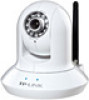
Wireless Pan/Tilt Surveillance Camera
•
Do not keep the
Camera exposed to
direct sunlight.
•
Do not place the
Camera in high humidity
environments such as
in a kitchen.
•
Do not place the
Camera where there are
sharp temperatures such as
near an oven.
•
Do not place the camera
near devices that emit
radio waves, such as
mobile phones.
Description
•
Solid
:
Th
e electrical
p
ower is on
.
•
Off
:
Th
ere is no electrical
p
ower
.
•
Solid
:
Th
e E
th
ernet
p
ort is
link
e
d, b
ut
th
ere is no activit
y.
•
Blinking:
There is traffic between the Ethernet port and
the
netw
ork.
•
Off
:
Th
ere is no E
th
ernet connection
.
MODEL NO.
TL-SC4171G
Camera
Mounting Bracket
Power Adapter
The following operating systems are supported:
The following browsers are supported:
• Windows XP
• Windows Vista
• Windows 7
• Windows 98
• Windows 2000
• Windows 2003
• Windows Me
• Mac
• Linux
• Microsoft Internet Explorer
• FireFox
• Safari
• Chrome
Ethernet Cable
Quick Installation Guide
Hardware Connection
4
Router
Internet
WAN
LAN
1
2
3
NOTE
: Before proceeding, confirm that your PC is connected
to your router and can access the Internet. Also confirm that
your router’s DHCP feature is enabled. (Most routers have
DHCP turned on by default.) For detailed information, please
refer to the operation instructions included with your router.
Camera Mounting
3
Antenna Connector
Audio Out
Reset Button
General I/O Terminal Block
Power Connector
Audio In
Network Connector
Power LED
Ethernet LED
Built-in Microphone
Ceiling Mount
Wall Mount
1
2
1
2
Fix the camera to the bracket
with two type A screws
.
Fix the bracket and camera
to the ceiling using
two
type B screws and two
hollow ceiling anchors.
Fix the bracket to the wall
using
two type B screws and
two hollow wall anchors.
Fix the camera to the bracket
with two type A screws .
12V DC
Audio in
Audio out
Ethernet
I/O
reset
12V DC
Audio in
Audio out
Ethernet
I/O
reset
Reset Button
Bracket
Type A screws
Type B screws
Hollow anchors
NOTE
: In the bracket,
there are several mounting holes arranged in a circle. The direction of the camera’s
installation can be anywhere within a 360 degree scope, adjusted as required.
It is strongly recommended that you connect the Ethernet cable and power adapter cord to the camera first
before mounting.
Item
Power LED
Ethernet LED
•
Step 1
: Re-power on the camera and wait for at least 45s
until it restarts up normally.
•
Step 2
: Press the button for more than 10s, then it will be
restored to factory defaults after automatic rebooting.
7106503435
Power Cable
Wireless Pan/Tilt Surveillance Camera
Quick Installation Guide
Ethernet Cable
(*The pictures are for reference only.)