TP-Link TL-SL5428E Quick Installation Guide
TP-Link TL-SL5428E Manual
 |
UPC - 845973020873
View all TP-Link TL-SL5428E manuals
Add to My Manuals
Save this manual to your list of manuals |
TP-Link TL-SL5428E manual content summary:
- TP-Link TL-SL5428E | Quick Installation Guide - Page 1
Quick Installation Guide TL-SL5428E 24-port 10/100Mbps + 4-port Gigabit L2 Managed Switch Rev 1.0.0 - TP-Link TL-SL5428E | Quick Installation Guide - Page 2
such as translation, transformation, or adaptation without permission from TP-LINK TECHNOLOGIES CO., LTD. Copyright © 2010 TP-LINK TECHNOLOGIES CO., LTD. All rights reserved. http://www.tp-link.com Technical Support Tel: +86 755 26504400 E-mail: [email protected] Monday to Friday 8:30 to 18:00 - TP-Link TL-SL5428E | Quick Installation Guide - Page 3
The following items should be found in your box: ¾ One L2 Managed Switch ¾ One Power Cord ¾ One Console Cable ¾ One Ground Cable ¾ This Quick Installation Guide ¾ Resource CD for the Switch, including: • User Guide • Other Helpful Information ¾ Two mounting brackets and the fittings Note: Make - TP-Link TL-SL5428E | Quick Installation Guide - Page 4
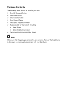
A: Specifications This appendix provides the Switch's technical specifications. 2. Conventions The Switch or TL-SL5428E mentioned in this Quick Installation Guide stands for TL-SL5428E 24-port 10/100Mbps + 4-port Gigabit L2 Managed Switch without any explanation. Symbol Description Note - TP-Link TL-SL5428E | Quick Installation Guide - Page 5
3 2.2.1 Desktop Installation 4 2.2.2 Rack Installation 4 2.3 Connect to Ground 5 Chapter 3 Connection 8 3.1 Ethernet Ports 8 3.2 SFP Ports 8 3.3 Console Port 9 3.4 Power On 10 Chapter 4 Login to the Switch 11 4.1 Login 11 4.2 Configuration 11 FAQ ...13 Appendix A: Specifications 14 - TP-Link TL-SL5428E | Quick Installation Guide - Page 6
Chapter 1 Product Introduction 1.1 Product Overview TP-LINK L2 Managed Switch provides both Web and Command Line management interface. The Embedded Web Interface supports remote configuration, monitoring and troubleshooting. The EIA-standardized framework together with smart configuration capacity - TP-Link TL-SL5428E | Quick Installation Guide - Page 7
The linked device is running at 10/100Mbps. 1.3 Rear Panel The rear panel of TL-SL5428E features a power socket and a Grounding Terminal (marked with ). Figure 1-2 Rear Panel ¾ Grounding Terminal: TL-SL5428E already comes with Lightning Protection Mechanism. You can also ground the Switch through - TP-Link TL-SL5428E | Quick Installation Guide - Page 8
Location Requirements When you choose a location for the Switch, please follow these guidelines: • Install the Switch on a flat and stable surface that can support the entire weight of the Switch with all fittings. • Locate the Switch far from strong electromagnetic field generators (such as motors - TP-Link TL-SL5428E | Quick Installation Guide - Page 9
Switch on a flat surface strong enough to support the entire weight of the Switch with all fittings. 2) Remove the adhesive backing papers from the rubber feet. 3) Turnover the Switch Switch. 2.2.2 Rack Installation To install the Switch in an EIA standard-sized, 19-inch rack, follow the instructions - TP-Link TL-SL5428E | Quick Installation Guide - Page 10
to the rack, as illustrated in the following figure. Figure 2-3 Mounting Switch 3) Connect the Switch to network devices. 4) Supply power to the Switch with the provided power cord. 2.3 Connect to Ground Connecting the Switch to ground is to quickly release the lightning over-voltage and over - TP-Link TL-SL5428E | Quick Installation Guide - Page 11
electric shock. In different environments, the Switch may be grounded differently. The following will instruct you to connect the Switch to the ground in two ways, connecting to the Grounding Bar or connecting to the Ground via the power cord. Please connect the Switch to ground in the optimum way - TP-Link TL-SL5428E | Quick Installation Guide - Page 12
your situation will comply with the regulation in your country, so they may differ from the figure above. Note: If you intend to connect the Switch to the ground via the PE (Protecting Earth) cable of AC power cord, please make sure the PE (Protecting Earth) cable in the electrical outlet - TP-Link TL-SL5428E | Quick Installation Guide - Page 13
shown. Figure 3-1 Connecting the RJ45 Port 3.2 SFP Ports The Switch features two SFP (Small Form-Factor Pluggable) transceiver slots that are valid link on the port, the associated RJ45 port will be disabled and cannot be used. Note: TL-SL5428E supports 100/1000Base-FX SFP module at full-duplex mode - TP-Link TL-SL5428E | Quick Installation Guide - Page 14
Caution: The serial port of the computer doesn't support plug-and-play feature, please make sure the Switch is powered off before connecting the console cable to the computer. Connect the console port of the Switch and your computer with a console cable as shown in Figure 3-3. Figure 3-3 Connecting - TP-Link TL-SL5428E | Quick Installation Guide - Page 15
so they may differ from the figure above. Powering on the Switch, it will automatically initialize and its LED indicators will respond as LED indicators will flash momentarily and then turn off, which represents a resetting of the system. 2) The PWR LED indicator will light on all the - TP-Link TL-SL5428E | Quick Installation Guide - Page 16
be set in the same subnet addresses of the Switch. The IP address is 192.168.0.x ("x" is any number from 2 to 254), Subnet Mask is 255.255.255.0. For the detailed instructions as to how to do this, please refer to Appendix B in the User Guide on the Resource CD. 2) After a moment, a login window - TP-Link TL-SL5428E | Quick Installation Guide - Page 17
Figure 4-3 Main Setup-Menu 12 - TP-Link TL-SL5428E | Quick Installation Guide - Page 18
the following items: 1) Check per port LED on the Switch and make sure the cable is installed properly. 2) Make sure the IP address of your PC is set in the same subnet addresses of the Switch. Restore the Switch to its factory defaults. And then the IP address can be set as 192.168.0.x ("x" is any - TP-Link TL-SL5428E | Quick Installation Guide - Page 19
A: Specifications IEEE 802.3 10Base-T Ethernet Standards IEEE 802.3u 100Base-TX/100Base-FX Fast Ethernet IEEE 802.3ab 1000Base-T Gigabit Ethernet IEEE 802.3z 1000Base-X Gigabit Ethernet IEEE 802.3x Flow Control 10Base-T: UTP/STP of Cat. 3 or above Transmission Medium 100Base-TX: UTP/STP - TP-Link TL-SL5428E | Quick Installation Guide - Page 20
7106503072
-
 1
1 -
 2
2 -
 3
3 -
 4
4 -
 5
5 -
 6
6 -
 7
7 -
8
-
9
-
10
-
11
-
12
-
13
-
14
-
15
-
16
-
17
-
18
-
19
-
20
 |
 |

Quick Installation Guide
TL-SL5428E
24-port 10/100Mbps + 4-port Gigabit
L2 Managed Switch
Rev 1.0.0