TP-Link TL-WA801ND User Guide - Page 61
Diagnostic, Set Community - v2
 |
UPC - 845973051419
View all TP-Link TL-WA801ND manuals
Add to My Manuals
Save this manual to your list of manuals |
Page 61 highlights
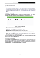
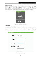
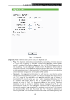
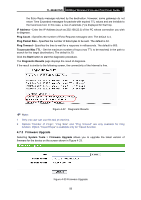
TL-WA801ND 300Mbps Wireless N Access Point User Guide ¾ SNMP Agent - Select the radio button before Enable will enable this function if you want to have remote control through SNMPv1/v2 agent with MIB-II. Select the radio button before Disable will disable this function. The default setting is Disable. ¾ SysContact - The textual identification of the contact person for this managed node. ¾ SysName - An administratively-assigned name for this managed node. ¾ SysLocation - The physical location of this node. ) Note: Specifying one of these values via the Device's Web-Based Utility makes the corresponding object read-only. If there isn't such a config setting, then the write request will succeed (assuming suitable access control settings), but the new value would be forgotten the next time the agent was restarted. ¾ Get Community - Enter the community name that allows Read-Only access to the Device's SNMP information. The community name can be considered a group password. The default setting is "public". ¾ Get Source - Get source defines the IP address or subnet for management systems that can read information from this 'get' community device. ¾ Set Community - Enter the community name that allows Read/Write access to the Device's SNMP information. The community name can be considered a group password. The default setting is "private". ¾ Set Source - Set source defines the IP address or subnet for management systems that can control this 'set' community device. ) Note: A restricted source can be a specific IP address (e.g. 10.10.10.1), or a subnet - represented as IP/BITS (e.g. 10.10.10.0/24). If an IP Address of 0.0.0.0 is specified, the agent will accept all requests under the corresponding community name. Click the Save button to save your settings. 4.7.2 Diagnostic Selecting System Tools > Diagnostic allow you to check the connections of your network components on the screen shown in Figure 4-31. 54
-
 1
1 -
2
-
3
-
4
-
5
-
6
-
7
-
8
-
9
-
10
-
11
-
12
-
13
-
14
-
15
-
16
-
17
-
18
-
19
-
20
-
21
-
22
-
23
-
24
-
25
-
26
-
27
-
28
-
29
-
30
-
31
-
32
-
33
-
34
-
35
-
36
-
37
-
38
-
39
-
40
-
41
-
42
-
43
-
44
-
45
-
46
-
47
-
48
-
49
-
50
-
51
-
52
-
53
-
54
-
55
-
 56
56 -
 57
57 -
 58
58 -
 59
59 -
 60
60 -
 61
61 -
 62
62 -
 63
63 -
 64
64 -
 65
65 -
 66
66 -
67
-
68
-
69
-
70
-
71
-
72
-
73
-
74
-
75
-
76
 |
 |