Thermador HPWB30FS Installation Instructions
Thermador HPWB30FS Manual
 |
View all Thermador HPWB30FS manuals
Add to My Manuals
Save this manual to your list of manuals |
Thermador HPWB30FS manual content summary:
- Thermador HPWB30FS | Installation Instructions - Page 1
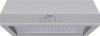
INSTALLATION MANUAL MODELS: HPWB30 HPWB36 HPWB48 LI3FEA Ed.04/08 - Thermador HPWB30FS | Installation Instructions - Page 2
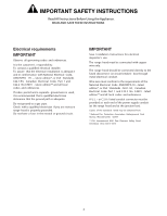
Local Electrical Inspector's use. INSTALLER: Please leave these Instructions with this unit for the owner. OWNER: Please retain these instructions for future reference. Safety Warning: Turn off power circuit at service panel and lock out panel, before wiring this appliance. Requirement: 120 V AC, 60 - Thermador HPWB30FS | Installation Instructions - Page 3
Always leave safety grills and filters in place. Without these components, operating blowers could catch onto hair, fingers and loose clothing. The manufacturer declines all responsibility in the event of failure to observe the instructions given here for installation, maintenance and suitable use - Thermador HPWB30FS | Installation Instructions - Page 4
grounded. Do not have a fuse in the neutral or ground circuit. IMPORTANT Save Installation Instructions for electrical inspector's use. The range hood must be connected with copper wire only. The range hood should be connected directly to the fused disconnect (or circuit breaker) box through metal - Thermador HPWB30FS | Installation Instructions - Page 5
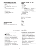
• Use & Care / Installation Instructions • Fittings bag with: 4 Washers 6 Drywall anchors 2 Hooks with regulating screws 6 S crews 5X35 4 Screws for transition Optional accessory Duct cover s Ductless recirculation kit available only for HPWB30 model. Parts Not Included with your Hood • Duct Tape - Thermador HPWB30FS | Installation Instructions - Page 6
Ceiling *Deflector Lamp Hood 30" to 36" Examples of possible ducting Round duct Transition Blower *Charcoal filters Filter Ceiling Lamp Hood * Charcoal filters 30" to 36" Transition Blower Filter RECIRCULATING * Optional accessory - Ductless recirculation kit * Only for 30" model VERTICAL - Thermador HPWB30FS | Installation Instructions - Page 7
exceed maximum permissable equivalent lengths! Maximum recommended duct length for these hoods: 150 feet Flexible ducting: If flexible metal ducting is used, safety standards such as those published by NFPA and ASHRAE. *Hoods are supplied with a 10" round transition. A locally supplied transition - Thermador HPWB30FS | Installation Instructions - Page 8
conduit cut outs, see figures 1 and 2 as needed. Model 30" 36" 48" X 2-3/4" 4-9/16" 10-9/16" X 10-1/2 22 5- 7/8" 2. Assembly of the 10" transition: The transition supplied with the hood mounts to the top. Do not install transition until hood is fixed on cabinet or wall. a. Place the transition - Thermador HPWB30FS | Installation Instructions - Page 9
height has been determined draw a horizontal line at a distance above the cooktop equal to the desired hood installation height plus 7- 1/2". See also Figure 4a. 4. Find the centerline of the cooktop. Draw a vertical line along this centerline up to the horizontal line drawn in step 1 and - Thermador HPWB30FS | Installation Instructions - Page 10
and seal with tape. For both installation method: 10.Wiring the HOOD: WARNING: To Avoid Electrical Shock Hazard Turn off power at the service panel before wiring this unit. 120 VAC, 15 or 20 Amp circuit required. ELECTRICAL GROUNDING INSTRUCTIONS THIS APPLIANCE IS FITTED WITH AN ELECTRICAL JUNCTION - Thermador HPWB30FS | Installation Instructions - Page 11
for Heating, Refrigeration and Air conditioning les instructions d'installation, entretien et utilisation, fournies avec l'appareil ne seraient pas observées. Le fabricant décline également toute responsabilité relative aux blessures produites àla suite de négligences de la part - Thermador HPWB30FS | Installation Instructions - Page 12
DE VOTRE APPAREIL. VEUILLEZ LIRE ET CONSERVEZ SOIGNEUSEMENT CES INSTRUCTIONS Spécifications pour l'installation électrique IMPORTANT Observez toutes les normes et réglementation en vigueur. Il est de la responsabilité du client : De faire installer l'appareil par un électricien dument qualifié. De - Thermador HPWB30FS | Installation Instructions - Page 13
5x35. •4 visses 2,9,6,5, pour connexion Accessoires optionnels Couvre-conduits Un kit de recyclage d'air sans conduit est disponible pour le modèle nuder les câbles •Des lunettes de sécurité •Des gants •Une échelle INSTALLATION DE LA HOTTE •Pour obtenir un maximum d'éfficacité en extraction de fumé - Thermador HPWB30FS | Installation Instructions - Page 14
du panneau de service et suffisement long pour arriver jusqu'àla hotte une fois installée. L'alimentation électrique doit correspondre aus spécifications suivantes : 120 V AC, 60 Hz. 15 ou 20 A. Exemples de possibles types d'extraction/evacuation Plafond Déflecteurr Lampe Hotte 30" a 36" Conduit - Thermador HPWB30FS | Installation Instructions - Page 15
domestique, tel qu'une hotte aspirante peut interrompre le cours normal de la combustion de l'air ainsi que la ventilation naturelle que demandent des installations telles que des cheminées - á bois ou á gaz ou encore les cheminées de chauffe-eau. Afin de minimiser les risques d'interruption de la - Thermador HPWB30FS | Installation Instructions - Page 16
Table 2. Instructions d'installation des conduits Pour des raisons de sécurité, l'exactration des fumées la connexion qui est fournie avec la hotte doit être installé sur le dessus. Ne pas installez cette connexion avant d'avoir fixé la hotte Model 30" 36" 48" sur le mur ou le meuble auquel elle - Thermador HPWB30FS | Installation Instructions - Page 17
suffisement long pour se brancher sur la connexion une fois la hotte installée. Rajoutez 1 ½pouces de plus àla longueur du conduit afin de connexion/transition sur la sortie supérieure. largeurdel'appareil. DIM. "W " DIM. "K " DIM. "Z" 30" 29 - 1/8" 2 - 1/2" 7 - 1/16" 36" 35 - 1/16" 2 - 1/2" 7 - Thermador HPWB30FS | Installation Instructions - Page 18
d'alimentation de 120 V AC, 15 ou 20Amp. INSTRUCTIONS DE MISE Á LA TERRE Cet appareil est équip être branché àla ligne de terre de l'installation électrique de votre maison et ne doit sous aucun ée àl'utilisation en luminaire ouvert. Mettez en service l'appareil en utilisant le panneau de commande. - Thermador HPWB30FS | Installation Instructions - Page 19
dentro de las paredes, techos, áticos, espacios sin uso o garajes. ADVERTENCIA PARA REDUCIR EL RIEGO DE FUEGO, UTILICE SÓLO DUCTOS DE METAL. Instale esta campana de acuerdo a todos los requerimientos especificados. ADVERTENCIA Para reducir el riesgo de fuego o descarga eléctrica, no use esta campana - Thermador HPWB30FS | Installation Instructions - Page 20
IMPORTANTES Read All Instructions Before Using the Appliance. READ AND SAVE THESE INSTRUCTIONS Requerimientos eléctricos IMPORTANTE /NFPA 70 última edición*, o Estándares CSA C22.1-94, Código Eléctrico Canadiense, Parte 1 y C22.2 No.0-M91 - última edición ** y todos los códigos y ordenanzas - Thermador HPWB30FS | Installation Instructions - Page 21
regulación de tornillos 6 Tornillos 5X35 4 tornillos para la transición 2,9,6,5 Accesorios opcionales Cubiertas de ductos Kit de recirculación disponible solo para el modelo HPWB30. Partes no incluidas en su campana • Cinta de ducto • 1/2" Conductor • Cables • Ductos redondos • Abrazaderas PRECAUCI - Thermador HPWB30FS | Installation Instructions - Page 22
Techo *Deflector Lámpara Campana 30" a 36" Ejemplos de posible intalación. Ductos Redondos. Transition Techo Blower *Filtros de Carbón. Filter Lámpara Campana * Filtros de Carbón 30" a 36" Transición Extractor. Filter RECIRCULANTE * Accesorio opcional - Kit de recirculación * Solamente para - Thermador HPWB30FS | Installation Instructions - Page 23
*Las campanas se suplen con una transición redonda de 10" Una transición se requiere para otras medidas. Nota: La salida en la parte alta de la campana es de 1/8" x 8". Pieza 10" redondo a 8" redondo Redondo, recto 3-1/4" x 10" 3-1/4" x 12 " recto codo 90° codo 45° 3 -1⁄4" x 12" 3-1/4" x 10" codo - Thermador HPWB30FS | Installation Instructions - Page 24
10-1/2 22 Model 30" 36" 48" X 2-3/4" 4-9/16" 10-9/16" Descarga Vertical. X Orificios de1-1/2" de diámetro, para opción de conducto vertical. 2.Ensamble de la transición de 10" : La transición provista con la campana se coloca encima de la parte de arriba de ésta. No instale la transición hasta - Thermador HPWB30FS | Installation Instructions - Page 25
aproximadamente 1/2" de la parte baja de la superficie del gabinete y los tornillos. 6. Coloque el ducto de 10", lo suficientemente largo para alcanzar la transición una vez que la campana ha sido instalada más 1 1/2" pulgadas para conectar el ducto. Quite 1 de los 2 pivotes e instale el conector de - Thermador HPWB30FS | Installation Instructions - Page 26
la caja-j respectivamente. • Cierre la cubierta de la caja-j. Pasos finales de instalación 11.Instale los filtros de grasa, lámparas y bandejas de goteo, como se describe en la sección de Uso & Cuidado de este manual. Nota: Las lámparas no se suministran, use SOLAMENTE 120 Volt, 50 Watt (máximo) 50
-
 1
1 -
 2
2 -
 3
3 -
 4
4 -
 5
5 -
 6
6 -
 7
7 -
8
-
9
-
10
-
11
-
12
-
13
-
14
-
15
-
16
-
17
-
18
-
19
-
20
-
21
-
22
-
23
-
24
-
25
-
26
 |
 |

INSTALLATION MANUAL
MODELS:
HPWB30
HPWB36
HPWB48
LI3FEA
Ed.
04/08