Toshiba 20VL14 Service Manual
Toshiba 20VL14 Manual
 |
View all Toshiba 20VL14 manuals
Add to My Manuals
Save this manual to your list of manuals |
Toshiba 20VL14 manual content summary:
- Toshiba 20VL14 | Service Manual - Page 1
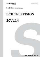
SERVICE MANUAL FILE NO. 050-200415 LCD TELEVISION 20VL14 DOCUMENT CREATED IN JAPAN, May, 2004 - Toshiba 20VL14 | Service Manual - Page 2
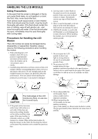
Table of Contents WARNINGS ...3 SERVICE SAFETY PRECAUTIONS ...4 Examples of Marks...4 HANDLING THE LCD MODULE ...5 Safety Precautions ...5 Precautions for Handling the LCD Module...5 LOCATION OF CONTROLS ...6 TV Front ...6 TV Rear...6 Remote Control ...7 LAYOUT OF MAJOR BOARDS ...8 MECHANICAL - Toshiba 20VL14 | Service Manual - Page 3
plug before starting work can result in electrical shock. Depending on the model, use an insulation transformer or wear gloves when servicing with the power on, and disconnect the power plug to avoid electrical shock when replacing parts. In some cases, alternating current is also impressed in the - Toshiba 20VL14 | Service Manual - Page 4
operational error. CAUTION Indicates a hypothetical situation in which service personnel and nearby third parties, or even end users after the service operation is completed, could possibly be in danger of injury The example shown to the left indicates that the power plug must be disconnected. 4 - Toshiba 20VL14 | Service Manual - Page 5
could result in freezing of the liquid crystal due to cold air or loss of resilience or other damage. CAUTION The metal edges of the LCD module are sharp, so use caution to avoid injury. 3. If the panel surface becomes soiled, wipe with cotton or a soft cloth. If this does not - Toshiba 20VL14 | Service Manual - Page 6
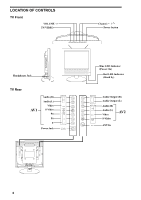
LOCATION OF CONTROLS TV Front VOLUME -/+ TV/VIDEO Headphones Jack TV Rear AV1 Audio (R) Audio (L) Video S-Video PR PB Y Power Jack Channel / Power button Blue LED Indicator (Power On) Red LED Indicator (Stand by) Audio Output (R) Audio Output (L) Audio (R) Audio (L) Video S-Video AV2 ANT - Toshiba 20VL14 | Service Manual - Page 7
Remote Control The illustration shown displays the Remote Control Buttons. POWER turns the TV on and off. MUTE turns the sound on and off. TV selects TV antenna as the input signal. AV1/AV2 selects the AV input signal from one of these connectors. Number Buttons allow direct access to channel - Toshiba 20VL14 | Service Manual - Page 8
LAYOUT OF MAJOR BOARDS Key/control board Main board Inverter board Light receiving board 8 - Toshiba 20VL14 | Service Manual - Page 9
MECHANICAL DISASSEMBLY B214 B215 A104 B211 A106 A108 B210 A102 B211 A107 9 - Toshiba 20VL14 | Service Manual - Page 10
B204 B209 B207 B208 B205 B214 B212 B203 B202 U004 B209 W601 B210 A101 U003 10 - Toshiba 20VL14 | Service Manual - Page 11
U902 B211 B206 U002 B208 U001 B201 E901 A105 11 - Toshiba 20VL14 | Service Manual - Page 12
PACKING DISASSEMBLY K901 Y150 Y151 Battery A702 Y101 Accessory Box LCD TV Set A703 A701 12 - Toshiba 20VL14 | Service Manual - Page 13
WIRING CONNECTION DIAGRAM Key/control board Inverter board Main board Light receiving board Right speaker Left speaker 13 - Toshiba 20VL14 | Service Manual - Page 14
CIRCUIT BOARD DIAGRAMS MAINBOARD 0171-4 14 - Toshiba 20VL14 | Service Manual - Page 15
15 - Toshiba 20VL14 | Service Manual - Page 16
0171-5 16 - Toshiba 20VL14 | Service Manual - Page 17
17 - Toshiba 20VL14 | Service Manual - Page 18
KEY/CONTROL BOARD LIGHT-RECEIVING BOARD 18 - Toshiba 20VL14 | Service Manual - Page 19
EARPHONE BOARD 19 - Toshiba 20VL14 | Service Manual - Page 20
components, read carefully the PRODUCT SAFETY NOTICE. Do not degrade the safety of the receiver through improper servicing. NOTES: 1. RESISTOR Resistance is shown in ohm [K = 1.000, M = 1.000.000]. enough sensitivity. 6. Voltage reading shown are nominal values and may vary ±20% except H.V. 20 - Toshiba 20VL14 | Service Manual - Page 21
MTS_OUT_L TV_M 11-TV_MTS I2C_SCL I2C_SDA I2C_SCL I2C_SDA +19V~12V PANEL_ON HIGH active SYS_ON LOW active AMP_POWER 13-Power TDA7499 HIGH active AUDIO_L_OUT AUDIO_R_OUT 08-Audio_AMP MUTE_AUDIO HIGH MUTE AUDIO_OUT_R AUDIO_OUT_L PANEL_ON SYS_ON AMP_POWER MUTE_AUDIO 02-MCU VOL_DOWN_KEY - Toshiba 20VL14 | Service Manual - Page 22
14.318MHZ/49US/DIP 1Y Y2 3G C246 27P/0603/NPO/50V VCC9 18 19 20 21 22 23 24 25 26 27 28 P3.6/WR P3.7/RD XTAL2 XTAL1 SA8 RESET JP1 1 2 3 4 5 6 7 8 9 10 11 12 13 14 15 16 17 18 19 20 21 22 NI SD0 SD2 SD4 SD6 ALE PSEN SA15 SA13 SA11 SA9 +5VSB I2C_SDA I2C_SCL J2 1 2 3 4 NI - Toshiba 20VL14 | Service Manual - Page 23
BB6 BB5 BB4 BB3 BB2 BB1 BB0 GB7 GB6 GB5 GB4 9 ALE 9 WR 9 RD 9 RST_SCALER 1 2 3 4 5 6 7 8 9 10 11 12 13 14 15 16 17 18 19 20 21 22 23 24 25 26 27 28 29 30 31 32 33 34 35 36 37 38 39 40 41 42 43 44 45 - Toshiba 20VL14 | Service Manual - Page 24
1 7 13 25 38 44 VCC VCC VCC VCC VCC VCC 21 22 23 24 27 28 29 30 31 32 20 19 A0 A1 A2 A3 A4 A5 A6 A7 A8 A9 A10 A11 14 36 DQM0 DQM1 17 16 15 18 35 1 7 13 25 38 44 VCC VCC VCC VCC VCC VCC 21 22 23 24 27 28 29 30 31 32 20 19 A0 A1 A2 A3 A4 A5 A6 A7 A8 A9 A10 A11 14 36 DQM0 DQM1 17 16 15 18 35 - Toshiba 20VL14 | Service Manual - Page 25
Y5V/16V 14 7 RST_VideoDecoder 15 16 17 18 19 9 I2C_SCL 1,2,3,6,9,10,14 I2C_SDA 20 21 22 23 24 L50 104P/0603/Y5V/50V B1 G1 R1 B2 G2 R2 16V 473P/0603/X7R/50V 0/0805 L42 MLB-160808-0600A-N2/0805 R223 1M/0603 Y5 20.25MHZ/49US/DIP L45 G 1Y Y2 3 C313 3P3/0603/NPO/50V C314 3P3/0603/ - Toshiba 20VL14 | Service Manual - Page 26
V-CHIP & CC VCC R230 4.7K/0603 12 3230_HS R231 10K/0603 1 Q33 SMBT3904/SOT23 SMD 2 3 R232 3.3K/0603 R233 6.8K/0603 R234 6.8K/0603 OSDB 12 OSDG 12 R235 6.8K/0603 1.5K/0603 1.5K/0603 OSDR 12 R236 R237 L54 C345 R238 VCC 1.5K/0603 MLB-160808-0120L-N2/0603 100P/0603/NPO/50V C346 - Toshiba 20VL14 | Service Manual - Page 27
103P/0603/X7R/50V 3 F3 Woofer Filter 22 C257 393P/0603/Y5V/50V 4 FF2 Volume Filter 21 C259 393P/0603/Y5V/50V 5 F1 Vcc(9V) 20 C260 10UF/25V/4*5 6 Lch input Woofer LPF3 19 + 7 GND Woofer LPF2 18 C263 10UF/25V/4*5 8 Rch input Woofer LPF1 17 + C265 4.7uF/50V/5*11 9 Bias - Toshiba 20VL14 | Service Manual - Page 28
POWER AMPLIFIER 28 OFF_MUTE 6 Q25 1N4148(BAS32L)/SMD SMBT3906/SOT23 SMD D12 2 3 1 2 VAU R184 150/0805 D13 2 100UF/25V/6*11 C277 NI/0603 C281 NI/0603 AUDIO_OUT_L 5 AUDIO_OUT_R 5 GND GROUND Title POWER AMPLIFIER Size A4 Date: Document Number TDA7499 2X6W Sheet 11 of Rev 0.01 14 - Toshiba 20VL14 | Service Manual - Page 29
-R V1-L V1-R V2-L V2-R V3-L V3-R STV-L STV-R SCL SDA MUTE BIAS 38 Lout1 36 Rout1 35 Lout2 26 Rout2 24 S2 S1 ADR 12 6 20 GND GND GND 28 22 33 100/0603 R146 MM1492A SMD NI/0603 C142 22uF/16V/4*5 R135 5.1K/0603 R136 5.1K/0603 AUDIO_OUT_L AUDIO_OUT_R VCC9A - Toshiba 20VL14 | Service Manual - Page 30
NTSC TUNER 30 U4 TUNER FQ1236_MK3 CASE CASE CASE CASE NC NC SIF CVBS +5V AF/MPX NC NC +5V SCL SDA AS 15 16 17 18 9 10 11 12 13 14 1 2 3 4 5 6 C361 220P/0603/NPO/50V + R51 NI/0603 R52 0/0603 TV_M 2 R53 100/0603 R54 100/0603 C362 220P/0603/NPO/50V IS =120mA + L62 NL252018 3.3UH/ - Toshiba 20VL14 | Service Manual - Page 31
SDA/SAPID 24 10 FOMO STERO REF 23 11 MUTE SIFREF 22 104P/0603/X7R/16V C54 12 SIF/B.B. 13 NOISE DET INPUT 21 NC 20 R44 4.7K/0603 R45 100/0603 + C48 33uF/50V/5*7 I2C_SCL 9 R47 100/0603 C50 2.2uF/50V/4*7 I2C_SDA 1,3,6,9,10,12,14 + + + C51 4.7uF/50V/5*11 C52 - Toshiba 20VL14 | Service Manual - Page 32
PBA1 PBA0 CN19 1 2 3 4 5 6 7 8 9 10 11 12 13 14 15 16 17 18 19 20 21 22 23 24 25 26 27 28 29 30 31 32 33 34 35 36 37 38 39 40 41 PHS PVS U12 1 2 3 4 5 6 7 8 9 10 11 12 13 14 15 16 17 18 19 20 21 22 23 24 25 26 27 28 VDD TXIN5 TXIN6 TXIN7 GND TXIN8 TXIN9 TXIN10 VDD TXIN11 TXIN12 TXIN13 GND TXIN14 - Toshiba 20VL14 | Service Manual - Page 33
POWER SYSTEMS + 33 CN1 VIN GND NC 1 2 3 DC_JACK 2.1 90D R57 NI/1206 LF1 1 PS PF 2 VFL C73 104P/ 470UF/25V/8*14 1 102P/0603/X7R/50V 8.2K/0603 10K/0603 D4 SS14(1N5819) SMD R97 1K/0603 1% Title POWER SYSTEMS 2 Size Document Number TL1451 / CEM9435A Rev 0.01 Date: Sheet 4 of 14 - Toshiba 20VL14 | Service Manual - Page 34
C110 104P/0603/Y5V/50V C111 104P/0603/Y5V/50V C112 104P/0603/Y5V/50V C113 104P/0603/Y5V/50V C114 104P/0603/Y5V/50V C115 104P/0603/Y5V/50V 10K/0603 R98 I/O CONNECTOR + 34 9 POWER_KEY 9 CH_UP_KEY 9 CH_DOWN_KEY 9 VOL_UP_KEY 9 VOL_DOWN_KEY 9 INPUT_KEY POWER_KEY CH_UP_KEY CH_DOWN_KEY VOL_UP_KEY - Toshiba 20VL14 | Service Manual - Page 35
HD2-OUT DGND NC HD1-OUT 30 29 28 27 26 25 24 23 22 21 20 19 18 17 16 C33 R32 R33 + + C32 1uF/50V/5*11 1uF/50V/5*11 SOT23 + 3 22uF/25V/4*5 R40 R41 5.1K/0603 1K/0603 0171-4 TOSHIBA USA Version For AU 20" Panel Title USA 480P Size Document Number Rev MST9883 0 Date: Sheet 1 of 14 35 - Toshiba 20VL14 | Service Manual - Page 36
IR BOARD CN1 1 2 3 4 5 6 CON5 5VSB D5 3 2 1 VCC COM GND U1 IR_RECIVER 5VSB R1 100 VCC GND S_OUT BAV99/SMD 5VSB 3 2 1 5VSB D3 3 2 1 VCC COM GND BAV99/SMD D1 LED_R RED 5VSB D4 3 2 1 VCC COM GND BAV99/SMD D2 LED_B BLUE + C1 C2 100UF/10V 104 36 - Toshiba 20VL14 | Service Manual - Page 37
EARPHONE BOARD 37 CN1 L_EAR 7 680£[/DIP 1/8W R1 R_SPK 6 L_SPK 5 R_EAR 4 680£[/DIP 1/8W R2 L_OUT 3 R_OUT 2 GND 1 EARPHONE J1 1 2 3 4 5 6 7 8 SPK_R_IN GND SPK_L_IN GND AUDIO_L_IN GND AUDIO_R_IN GND B5B-PH-K AUDIOGND - Toshiba 20VL14 | Service Manual - Page 38
KEYPAD BOARD 1 S1 S1 3 2 S2 S2 4 1 S1 S1 3 2 S2 S2 4 1 S1 S1 3 2 S2 S2 4 1 S1 S1 3 2 S2 S2 4 1 S1 S1 3 2 S2 S2 4 1 S1 S1 3 2 S2 S2 4 SW1 SW_TACT SW2 SW_TACT SW3 SW_TACT SW4 SW_TACT SW5 SW_TACT SW6 SW_TACT POWER_KEY CH_UP_KEY CH_DOWN_KEY VOL_UP_KEY VOL_DOWN_KEY INPUT_KEY J1 7 6 5 4 3 2 1 - Toshiba 20VL14 | Service Manual - Page 39
servicing. NOTICE: The part number must be used when ordering parts, in order to assist in processing, be sure to include the Model number and Description. 20VL14 Safety Location No. TOSHIBA -T000EN1411 EFB1-5534200000 Hinge Hinge 20VL14 User's Manual-(20VL14)CN14 GT140/201A English 210x297mm - Toshiba 20VL14 | Service Manual - Page 40
Safety Location No. TOSHIBA SN Parts No. (GOLANA) Description Y151 72001926 EW12-HUS2000000 AC Power Cord K901 72001927 EFA1-8640014000 Remote Control-English E901 72001928 EPBT-201TAU0005 Panel TFT W601 72001890 EF61-3400500603 Square Speaker 20"(B) Specification SP-12A+IS-038A L=2M CT- - Toshiba 20VL14 | Service Manual - Page 41
Control (CT-864) and two "AAA" batteries Power cord AC adapter (TAA-Y58) (The AC adapter can be only used for this LCD TV. Do not use for other apparatus.) Owner's Manual Design and specifications are subject to change without notice. LCD display panels are manufactured using an extremely high - Toshiba 20VL14 | Service Manual - Page 42
TOSHIBA CORPORATION 1-1, SHIBAURA 1- CHOME, MINATO-KU, TOKYO 105-8001, JAPAN
-
 1
1 -
 2
2 -
 3
3 -
 4
4 -
 5
5 -
 6
6 -
 7
7 -
8
-
9
-
10
-
11
-
12
-
13
-
14
-
15
-
16
-
17
-
18
-
19
-
20
-
21
-
22
-
23
-
24
-
25
-
26
-
27
-
28
-
29
-
30
-
31
-
32
-
33
-
34
-
35
-
36
-
37
-
38
-
39
-
40
-
41
-
42
 |
 |
SERVICE MANUAL
FILE NO. 050-200415
20VL14
LCD TELEVISION