Toshiba 65HM167 Service Manual - Page 36
Verifying Audio
 |
UPC - 022265000496
View all Toshiba 65HM167 manuals
Add to My Manuals
Save this manual to your list of manuals |
Page 36 highlights
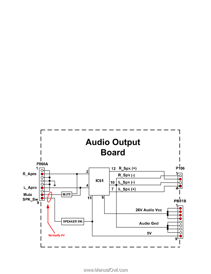
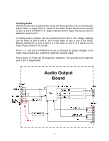
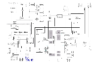
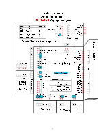
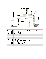
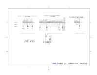
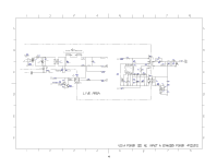
Verifying Audio Distorted audio can be approached using the drawing below and an oscilloscope, signal tracer, or signal injector. Inputs to the Audio Output board can be scoped on pins 2 and 6 of P860A or B. Signal injection and/or signal tracing can also be applied to pins 2 and 6. A missing audio symptom can be scoped at pins 2 and 6. DC voltage readings can be taken at pins 8 and 9. The normal state of pins 8 and 9 are 0VDC. Missing waveforms on pins 2 and 6 or a DC level on pins 8 or 9 will tell us the Audio Output board is not at fault. Pins 1 - 4 and pin 9 of PB81B or A can be checked for proper voltages to the Audio Output board and scoped for distortion causing ripple. Pins 2 and 4 of P106 can be scoped for distortion. The grounds to be used are pins 1 and 3, respectively. Return to Table of Contents Continue to Next Page ” 2007 Toshiba America Consumer Products, LLC. 11 of 12 35 SMART2007003_Version 20Q DLP_1.0.4
-
 1
1 -
2
-
3
-
4
-
5
-
6
-
7
-
8
-
9
-
10
-
11
-
12
-
13
-
14
-
15
-
16
-
17
-
18
-
19
-
20
-
21
-
22
-
23
-
24
-
25
-
26
-
27
-
28
-
29
-
30
-
 31
31 -
 32
32 -
 33
33 -
 34
34 -
 35
35 -
 36
36 -
 37
37 -
 38
38 -
 39
39 -
 40
40 -
 41
41 -
42
-
43
-
44
-
45
-
46
-
47
 |
 |