Toshiba MW27F51 Service Manual
Toshiba MW27F51 Manual
 |
View all Toshiba MW27F51 manuals
Add to My Manuals
Save this manual to your list of manuals |
Toshiba MW27F51 manual content summary:
- Toshiba MW27F51 | Service Manual - Page 1
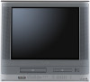
FILE NO. 140-200509 (MFR'S VERSION A) SERVICE MANUAL COLOR TELEVISION/ VIDEO CASSETTE RECORDER/ DVD VIDEO PLAYER MW27F51 DOCUMENT CREATED IN JAPAN, April, 2005 - Toshiba MW27F51 | Service Manual - Page 2
TO ENSURE PROPER USE OF THIS PRODUCT, PLEASE READ THIS SERVICE MANUAL CAREFULLY AND RETAIN FOR FUTURE REFERENCE. SHOULD THE UNIT REQUIRE MAINTENANCE, CONTACT AN AUTHORIZED SERVICE LOCATION-SEE SERVICE PROCEDURE. USE OF CONTROLS, ADJUSTMENTS OR THE PERFORMANCE OF PROCEDURES OTHER THAN THOSE SPECIFIED - Toshiba MW27F51 | Service Manual - Page 3
when you order parts. (Particularly the VERSION LETTER.) 1. MODEL NUMBER and VERSION LETTER The MODEL NUMBER can be found on the back of each product and the VERSION LETTER can be found at the end of the SERIAL NUMBER. 2. PART NO. and DESCRIPTION You can find it in your SERVICE MANUAL. A1-2 - Toshiba MW27F51 | Service Manual - Page 4
sources, refer to the operating instructions. 11. GROUNDING OR POLARIZATION This unit is equipped with a polarized alternating-current line plug (a plug having one they may touch dangerous voltage points or short out parts that could result in fire or electric shock. Never spill or spray any type - Toshiba MW27F51 | Service Manual - Page 5
parts. Unauthorized substitutions may result in fire, electric shock or other hazards. 21. SAFETY CHECK Upon completion of any service or repairs to this unit, ask the service injury. Read the owner's manual of the other equipment carefully and follow the instructions when making any connections - Toshiba MW27F51 | Service Manual - Page 6
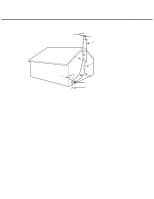
IMPORTANT SAFEGUARDS (CONTINUED) EXAMPLE OF ANTENNA GROUNDING AS PER THE NATIONAL ELECTRICAL CODE GROUND CLAMP ELECTRIC SERVICE EQUIPMENT NEC-NATIONAL ELECTRICAL CODE S2898A ANTENNA LEAD IN WIRE ANTENNA DISCHARGE UNIT (NEC SECTION 810-20) GROUNDING CONDUCTORS (NEC SECTION 810-21) GROUND CLAMPS - Toshiba MW27F51 | Service Manual - Page 7
on the short circuit position after the connection of Pick Up PCB and DVD PCB connector. NOTE • Before your operation, please read "PREPARATION OF SERVICING". • Use the Lead Free solder. • Manual soldering conditions • Soldering temperature: 320 ± 20˚C • Soldering time: Within 3 seconds • Soldering - Toshiba MW27F51 | Service Manual - Page 8
Remove the TV/DVD/VCR block from the main unit as shown in Fig. 1 below can be seen. (Refer to item 1 of the DISASSEMBLY INSTRUCTIONS.) 2. Fig. 2 DISC REMOVAL METHOD AT NO POWER SUPPLY 1. Remove the Back Cabinet and TV/DVD/VCR Block. (Refer to item 1 of the DISASSEMBLY INSTRUCTIONS.) 2. Rotate - Toshiba MW27F51 | Service Manual - Page 9
the steps below. 1. Turn Unit ON. 2. Set the DVD to the Stop Mode. 3. Check that 'No disc' is displayed on the screen. 4. Press and hold the 'STOP(DVD)' button on the front panel. 5. Simultaneously press and hold the '7' key on the remote control unit. 6. Hold both keys for more than 3 seconds - Toshiba MW27F51 | Service Manual - Page 10
control and adjust it to 650°F ± 20°F (350°C ± 10°C). In case of using high temperature soldering iron, please be carefull not to heat too long. • Pb free with the printed circuit board with PbF printing must be serviced with lead free solder. When soldering or unsoldering, completely remove all of - Toshiba MW27F51 | Service Manual - Page 11
...GENERAL SPECIFICATIONS ...DISASSEMBLY INSTRUCTIONS 1. REMOVAL OF MECHANICAL PARTS AND P. C. BOARDS 2. REMOVAL OF VCR DECK PARTS 3. REMOVAL OF DVD DECK PARTS 4. REMOVAL OF ANODE CAP ...5. REMOVAL AND INSTALLATION OF FLAT PACKAGE IC KEY TO ABBREVIATIONS ...SERVICE MODE LIST ...PREVENTIVE - Toshiba MW27F51 | Service Manual - Page 12
G-1 TV System G-2 VCR System G-3 DVD System G-4 Tuning System GENERAL SPECIFICATIONS CRT Color System Speaker Sound Output System Video System Hi-Fi STEREO NTSC PB Deck Heads Video Head CRT Size / Visual Size CRT Type Magnetic Field BV/BH Position Size Impedance MAX 10%(Typical) FM Audio - Toshiba MW27F51 | Service Manual - Page 13
SPECIFICATIONS G-5 Signal Video Signal RGB Signal Audio Signal VCR DVD Hi-Fi Audio Signal G-6 Power Power Source Power Consumption Protector G-7 Regulation G-8 Temperature G-9 Operating Humidity Input Level Output Level S/N Ratio (Weighted) at DVD Mode S/N Ratio (Weighted) at VCR - Toshiba MW27F51 | Service Manual - Page 14
Date Yes TV/VCR Yes DVD Yes CH/AV(LINE) Yes Tape Counter(Linear Counter) Yes Tape Speed Yes Sleep Time Yes Stereo/Audio Output Yes Bilingual No SAP Yes Control Volume Yes Level Brightness/Contrast/Sharpness/Color Yes Tint Yes Bass/Treble/Balance Yes Manual Tracking Yes - Toshiba MW27F51 | Service Manual - Page 15
(DVD) GENERAL SPECIFICATIONS Menu (DVD) Menu Type Language Menu Subtitle Audio OSD Language(Set up Language) Video E.B.L. (Enhanced Black Level) TV Screen Size(4:3) OSD Display On/Off Picture Mode (Video/Film/Auto) JPEG Interval Audio DRC (Dynamic Range Control) Dialogue (On DRC[TV - Toshiba MW27F51 | Service Manual - Page 16
Clock,Timer and Timer Back-up G-14 Remote Control Unit GENERAL SPECIFICATIONS Calendar Timer Events One Touch Recording Max Unit Glow in Dark Remocon Remocon Format Format Custom Code Power Source Voltage(D.C) UM size x pcs Total Keys Keys TV/VCR DVD Power 1 2 3 4 5 6 7 8 - Toshiba MW27F51 | Service Manual - Page 17
G-15 Features (TV/VCR) Features (DVD) GENERAL SPECIFICATIONS Auto Head Cleaning VIDEO PLUS+(SHOWVIEW,G-CODE) Auto Clock Picture Preference Auto Setup Forward / Reverse Picture Search Auto CH Memory Surround Stable Sound Closed Caption TV Auto Shut off Function End Call Index Search - Toshiba MW27F51 | Service Manual - Page 18
G-16 Accessories G-17 Interface G-18 Set Size G-19 Weight GENERAL SPECIFICATIONS Owner's Manual Language w/Guarantee Card Remote Control Unit Battery UM size x pcs OEM Brand Rod Antenna Poles Terminal Loop Antenna Terminal U/V Mixer 300 ohm to 75 ohm Antenna Adapter Antenna Change - Toshiba MW27F51 | Service Manual - Page 19
G-20 Carton G-21 Material G-22 Environment GENERAL SPECIFICATIONS Master Carton Content Material Dimensions W x D x H(mm) Description of Origin requirement (by buyer) Pb-free No - - - - Double/White 851 x 618 x 776 Yes 1 Corner / 2 Edges / 4 Surfaces 40(ORION SPEC:25) 156 Sets PS - Toshiba MW27F51 | Service Manual - Page 20
OR REPAIR ANY PCB, UNPLUG THE POWER CORD FROM THE AC SOURCE. 1. Remove the Anode Cap. (Refer to REMOVAL OF ANODE CAP) 2. Disconnect the following connectors: (CP802B, CP803 and CP852). 3. Remove the CRT PCB in the direction of arrow. Front Cabinet CP803 CP852 CRT PCB CP802B TV/DVD/VCR Block - Toshiba MW27F51 | Service Manual - Page 21
DISASSEMBLY INSTRUCTIONS 1-5: VCR DECK (Refer to Fig. 1-5) NOTE Do not remove the cable at the FE Head section. The FE Head may be damaged if you remove the cable by force. 1. Remove the 2 screws 1. 2. Remove the VCR Top. 3. Move the Cassette Holder Ass'y to the back side. 4. Remove the 3 screws 2. - Toshiba MW27F51 | Service Manual - Page 22
PCB DVD Top 1 1 DVD PCB 2 3 (A) 3 2 (C) CP2603 CP2602 CP2601 DVD Deck Angle Deck 2 2 Pick Up PCB (B) Short circuit using a soldering iron. Fig. 1-8 NOTE 1. Before your operation, please read "PREPARATION OF SERVICING". 2. Use the Lead Free solder. 3. Manual soldering conditions - Toshiba MW27F51 | Service Manual - Page 23
INSTRUCTIONS 2. REMOVAL OF VCR DECK PARTS 2-1: TOP BRACKET (Refer to Fig. 2-1) 1. Extend the 2 supports 1. 2. Slide the 2 supports 2 and remove the Top Bracket. NOTE 1. After the installation of the Top Bracket, bend the support Link Unit to the Eject position. 2. Unlock the support 1. 3. Remove the - Toshiba MW27F51 | Service Manual - Page 24
DISASSEMBLY INSTRUCTIONS 2-5: LOADING MOTOR/WORM (Refer to 3. Unlock the 2 supports 1 and remove the Tension Band. 4. Unlock the support 2 and remove the Tension Arm Ass'y. 5. Unlock the support 3 and remove the Loading Motor - + Pink White Capstan DD Unit L2 L1 Fig. 2-5-D Fig. 2-6-C B2-2 - Toshiba MW27F51 | Service Manual - Page 25
Connect DISASSEMBLY INSTRUCTIONS Tension Band clockwise and bend the hook section to remove it. 3. Unlock the 2 supports 1 and remove the T Brake Band. T Brake Band Idler Gear S the S Reel and T Reel installation, check if the correct parts are installed. (Refer to Fig. 2-8-B) 2. In case - Toshiba MW27F51 | Service Manual - Page 26
DISASSEMBLY INSTRUCTIONS 2-9: CASSETTE OPENER/PINCH ROLLER BLOCK/P5 ARM ASS'Y (Refer to Fig. 2-9-A) 1. Unlock the support 1 and remove the 2-11 2-12: CYLINDER UNIT ASS'Y (Refer to Fig. 2-12) 1. Unlock the support 1 and remove the AHC Ass'y. 2. Disconnect the following connector: (CD2001). 3. Remove - Toshiba MW27F51 | Service Manual - Page 27
DISASSEMBLY INSTRUCTIONS 2-13: CAPSTAN DD UNIT (Refer to Fig. 2-13) 1. Remove the Capstan Belt. 2. Remove the screw 1. 3. Remove the Capstan Holder. 4. Remove the 3 screws 2. 5. Remove the Capstan - Toshiba MW27F51 | Service Manual - Page 28
/LED REFLECTOR (Refer to Fig. 2-17-A) 1. Remove the P4 Cap. 2. Unlock the support 1 and remove the Cassette Guide Post. 3. Remove the Inclined Base S/T Unit. 4. Remove the screw 2. 5. Remove the LED Reflector. Cassette Guide Post 1 Loading Arm T Unit Loading Arm S Unit Fig. 2-15-B Inclined Base - Toshiba MW27F51 | Service Manual - Page 29
needed if the disassembly is done. If the repair is needed except listed parts, replace the DVD MECHA ASS'Y. 3-1: TRAY (Refer to Fig. 3-1-A) 1. Set the Tray opened. (Refer to the DISC REMOVAL METHOD AT NO POWER SUPPLY) 2. Unlock the 2 supports 1 and remove the Tray. 3-2: MAIN CHASSIS ASS'Y (Refer - Toshiba MW27F51 | Service Manual - Page 30
DISASSEMBLY INSTRUCTIONS 3-3: LOADING MOTOR PCB ASS'Y/ LOADING BELT (Refer to Fig. 3-3-A) 1. Remove the Loading to Fig. 3-4-A) 1. Press down the catcher 1 and slide the Rack Loading. 2. Unlock the support 2 and remove the Pulley Gear. 3. Remove the Main Gear. Pulley Gear Main Gear Rack Loading - Toshiba MW27F51 | Service Manual - Page 31
DISASSEMBLY INSTRUCTIONS NOTE 1. In case of the Clamper Ass'y installation, install correctly as Fig. 3-5-B. Clamper Plate Clamper No gap 3-7: SWITCH PCB ASS'Y/MIDDLE GEAR/FEED MOTOR (Refer to Fig. 3-7-A) 1. Remove the screw 1. 2. Remove the Switch PCB Ass'y. 3. Unlock the support 2. 4. Remove - Toshiba MW27F51 | Service Manual - Page 32
DISASSEMBLY INSTRUCTIONS Main Chassis Ass'y (Bottom Side) Check Hook Check Hook Check 3-8-A to Fig. 3-8-C. NOTE 1. Do not make the folding lines except the specified positions for the FFC. [ 24 pin FFC ] Fold back at the border line of the reinforcement plate. Printing Surface 50 ± 1mm 73 ± - Toshiba MW27F51 | Service Manual - Page 33
support. (Refer to Fig. 4-2.) Rubber Cap Fig. 4-4 4. Insert one end of the Anode Support into the anode button, then the other as shown in Fig. 4-5. CRT Support Support CRT Fig. 4-5 Fig. 4-2 5. Confirm that the Support is securely connected. 6. Put on the Rubber Cap without moving any parts - Toshiba MW27F51 | Service Manual - Page 34
DISASSEMBLY INSTRUCTIONS 5. REMOVAL AND INSTALLATION OF FLAT PACKAGE IC REMOVAL 1. Put Masking Tape (cotton tape) around the Flat Package IC to protect other parts from any damage. (Refer to Fig. 5-1.) NOTE Masking is carried out on all the parts located within 10 mm distance from IC leads. IC - Toshiba MW27F51 | Service Manual - Page 35
that no abnormality is found on the soldering position and installation position of the parts around the IC. If some abnormality is found, correct by resoldering. NOTE When the IC leads are bent during soldering and/or repairing, do not repair the bending of leads. If the bending of leads are - Toshiba MW27F51 | Service Manual - Page 36
White : Capacitance, Collector : Cassette : Capstan : Carrier : Channel : Clock : Clock (Syscon to Servo) : Combination, Comb Filter : Converter : Capstan Motor : Control : Generator : Ground H H.P.F H.SW Hz I IC IF IND INV K KIL LL LED LIMIT AMP LM : Radio Frequency : Remote Control : Relay : Serial - Toshiba MW27F51 | Service Manual - Page 37
Synchronization : Sync Separator, Separation : Transistor : Tracking : Trick Playback : Test Point : Unregulated : Volt : Voltage Controlled Oscillator : Video Intermediate Frequency : Vertical Pulse, Voltage Display : Video Playback : Variable Resistor : Video Recording : Visual Search Fast Forward - Toshiba MW27F51 | Service Manual - Page 38
SERVICE MODE LIST This unit is provided with the following SERVICE MODES so you can repair, examine and adjust easily. To enter to the SERVICE MODE function, press and hold both buttons simultaneously on the main unit or on the main unit and on the remote control for more than the standard time ( - Toshiba MW27F51 | Service Manual - Page 39
following list means standard hours, so the checking hours depends on the conditions. Time Parts Name Audio Control Head Full Erase Head (Recorder only) Capstan Belt Pinch Roller Capstan DD Unit Loading Motor Tension Band T Brake Band Clutch Ass'y Idler Arm Ass'y Capstan Shaft Tape Running Guide - Toshiba MW27F51 | Service Manual - Page 40
PREVENTIVE CHECKS AND SERVICE INTERVALS CLEANING NOTE After cleaning the heads with isopropyl alcohol, do not run a tape until the heads dry completely. If the heads are not completely dry and alcohol gets on the tape, damage may occur. 1. AUDIO CONTROL HEAD Clean the Audio Control Head with the - Toshiba MW27F51 | Service Manual - Page 41
) IC If a service repair is undertaken where it has been required to change the MEMORY IC, 97 8C 9F B7 88 91 B6 1A 0B 3D 04 27 16 27 30 30 05 31 18 FF 00 @ @ 3F 00 and set to the TV mode. 11. Press both VOL. DOWN button on the set and the Channel button (1) on the remote control for more than 2 - Toshiba MW27F51 | Service Manual - Page 42
SERVICING Part No. APJG002B00 APJG002E00 APJG002F00 APJG022000 APJG024A00 APJG153000 APJG185000 Parts on Playback PREPARATION FOR SERVICING 1. Set the VOLUME to VCR deck can be operated without a cassette tape.) 3. In case of using a cassette tape, press the STOP/EJECT button to insert or eject - Toshiba MW27F51 | Service Manual - Page 43
Adjust the adjusting section for the Tension Arm position so that the Tension Arm top is within the standard line of Main Chassis. 3. While turning the S Reel clockwise, confirm that the edge of the Tension Arm in SP mode. Tentelometer (JG185) Video Tape D2-1 P1 Post Guide Roller Fig. 1-3 - Toshiba MW27F51 | Service Manual - Page 44
Set to the Picture Search (Rewind) parts. Check item Replacement Part GUIDE ROLLER 1. Playback the VHS Alignment Tape. 2. Connect CH-1 of the oscilloscope to TP4501 (Envelope) and CH-2 to TP102 (SW Pulse). 3. Press both VOL. DOWN button on the set and the Channel button (5) on the remote control - Toshiba MW27F51 | Service Manual - Page 45
picture of Stamp Mark P4 Cap 2-3: TAPE RUNNING ADJUSTMENT (X VALUE ADJUSTMENT) 1. Confirm and adjust the height of the Reel Disk. (Refer to item 1-1) 2. Confirm and adjust the position of the Tension Post. (Refer to item 1-2) 3. Adjust the Guide button (5) on the remote control for more than 2 - Toshiba MW27F51 | Service Manual - Page 46
MECHANICAL ADJUSTMENTS 3. MECHANISM ADJUSTMENT PARTS LOCATION GUIDE 4 5 6 3 2 7 1 10 9 8 1. Tension Connect 2. Tension Arm 3. Guide Roller 4. Audio/Control Head 5. X value adjustment driver hole 6. P4 Post 7. T Brake Spring 8. T Reel 9. S Reel 10. Adjusting section for the Tension Arm - Toshiba MW27F51 | Service Manual - Page 47
repairing the circuits or replacing electrical parts or PCB assemblies. CAUTION • Use an isolation transformer when performing any service IC remote control for more than 2 seconds to appear the adjustment mode on the screen as shown in Fig. 1-1. TV TINT 27 SHARP BASIC ADJUSTMENTS (VCR SECTION) 2-1: - Toshiba MW27F51 | Service Manual - Page 48
Turn the Focus Volume fully counterclockwise once. 3. Adjust the Focus Volume until picture is distinct. horizontal line Notch Shadow mask Fig. 2-2 2-9: VERTICAL SIZE 1. Receive the monoscope pattern. 2. Using the remote control, set the brightness and contrast to normal position. 3. Activate the - Toshiba MW27F51 | Service Manual - Page 49
the adjustment mode display of Fig. 1-1 and press the channel button (31) on the remote control to select "TRAPEZIUM". 4. Press the VOL. UP/DOWN button on the remote control until the both vertical lines of the screen become parallel. 2-12: PARABOLA 1. Receive the crosshatch signal from the Pattern - Toshiba MW27F51 | Service Manual - Page 50
on the remote control until the red color level is adjusted to 110 ± 5% of the white level. (Refer remote control to set to the AV mode. Then perform the above adjustments 1~3. 5. Receive a broadcast and check if the picture is normal. Press the DVD button on the remote control to set to the DVD - Toshiba MW27F51 | Service Manual - Page 51
bar generator. 3. Slide the deflection yoke until it touches the funnel side of the CRT. 4. Adjust center of screen to green, with red and blue on the sides of 6 pole magnets. 8. Adjust the crosshatch pattern to change to white by repeating steps 6 and 7. 3-2: PURITY NOTE Adjust after performing - Toshiba MW27F51 | Service Manual - Page 52
2. ELECTRICAL ADJUSTMENT PARTS LOCATION GUIDE (WIRING CONNECTION) CD1702 AC IN CD001 J8007 J4202 J4201 R808 R804 TP806 R806 TP804 TP805 CD803 CD8101 CP8002 CP602 CD603 CD4501 J2204 J2203 J2202 J2201 CRT SPEAKER CP303 VR1701 CD303 CP4503 FE HEAD TP5501 TP4501 TP102 VCR PCB CD1704 - Toshiba MW27F51 | Service Manual - Page 53
DM III A, B, C, D, E, F Pick up RF CD, DVD, LD Loading Motor Spindle/ Sled Motor SPDL+/- READ CHANNEL IC2601 ZR36708TQC RFA_SDEN ALRCLK STEREO DAC IC8502 PCM1742 KEG/2K E-1 TV BLOCK TX RX P.CON+3.3V P.CON+5V P.CON+9V DVD CVBS DVD_C DVD_Y SPDIF-134 DVD RESET DVD_A_OUT_L DVD_A_OUT_R ZERO E-2 - Toshiba MW27F51 | Service Manual - Page 54
CONTROL 5 AUDIO PB 4 CTL+ 3 CTL- 2 AE HEAD(+) 1 AE HEAD(-) E-3 Y/C/AUDIO/HEAD AMP BLOCK DIAGRAM X4501 3.579545MHz Y/C/AUDIO/HEAD AMP IC BPF2 3.58M BPF1 PB AMP DOUBLE LIM FM DEM P R ALC DET MUTE LINE AMP LPF SUB LPF V-AGC ALC P P R R YNR/ COMB N.L. DVD IN/OUT CHROMA/IF MICON E-4 - Toshiba MW27F51 | Service Manual - Page 55
IC IC101 OEC8078A REGULATOR CHROMA/IF TV DIGITAL/ COMB FILTER DVD IN/OUT IN/OUT P.CON+5V_A VCR_POWER_H VCR_POWER_H POWER_FAIL AV_SW1 AV_SW2 AV_SW1 RX TX DVD SYNC 24 H.SW 23 C_ROTARY 98 Y/C CS 12 VCR.A.MUTE 54 H.AMP SW1 99 V.REC START-H 5V 21 34 21 MS_SEN A Q105 34 27 DVD_H 83 MS SEN-A 82 MS SEN - Toshiba MW27F51 | Service Manual - Page 56
STOP/EJECT PLAY FF REC/OTR CH.DOWN CH.UP OPEN/CLOSE VOL DOWN VOL UP SKIP STOP PLAY SKIP POWER MICON REMOCON_IN TV_POWER_H T-REC_LED REC_LED DVD IN/OUT JACK J2204 2 EXT_A_MUTE VCR_A_MUTE EXT_MUTE MICON SW_AUDIO_OUT_R SW_AUDIO_OUT_L DVD IN/OUT SOUND_R+ SOUND_L+ SP_OUT_R SP_OUT_L SOUND AMP/ - Toshiba MW27F51 | Service Manual - Page 57
COMB FSC Y/C_VIDEO_Y DVD IN/OUT DVD_Y/C_Y TV_POWER_H MICON EMERGENCY VM_OSD_SW VCR_POWER_H E-9 CHROMA/IF BLOCK DIAGRAM CHROMA/IF_ IC IC601 LA76324M 60 57 5V AT+5.7V REG MOTOR+12V 8.5V REG P.CON+8V MICON REGULATOR TV REGULATOR FROM TO CRT/SVM CP802 CUT OFF 1 R.OUT 3 G.OUT 4 B.OUT 5 - Toshiba MW27F51 | Service Manual - Page 58
REGULATOR P.CON+8V SOUND AMP/SURROUND BLOCK DIAGRAM SOUND AMP IC IC352 AN7522N 1 5968 2 12 4 10 Q350 MUTE SW 18 17 16 19 SURROUND-IC IC302 AN5891SA-E1V 31 30 3 SPEAKER SP351 SPEAKER SP352 SOUND_R+ SOUND_L+ SP_OUT_L SP_OUT_R IN/OUT SW_AUDIO_OUT_L SW_AUDIO_OUT_R DVD IN/OUT E-11 E-12 - Toshiba MW27F51 | Service Manual - Page 59
P.CON+5V_A P.CON+12V E-13 Hi-Fi/DEMODULATOR BLOCK DIAGRAM HI-FI AUDIO/H.AMP/DEM IC IC5501 AN3663FBP 22 AMP 24 AMP 21 AGC L/R REC MIX LPF INPUT SW VCO 1 2 BLOCK 29 28 27 25 36 40 LOGIC 42 51 43 58 56 AUDIO_OUT_R AUDIO_OUT_L DVD_A_OUT_R DVD_A_OUT_L DVD IN/OUT FRONT_A_IN_R - Toshiba MW27F51 | Service Manual - Page 60
TU001 115-V-KA35AR 3 10 11 12 14 15 17 AV SW IC IC1502 MM1501XNRE 6 2 1 3 4 AV SW IC IC1504 MM1501XNRE 6 2 1 3 4 VIDEO OUT SW IC IC1505 MM1504XNRE 6 2 1 3 4 E-15 COMB_FSC Y/C_VIDEO_Y SW_C CHROMA/IF DVD_Y/C-C DVD_VIDEO DVD IN/OUT Y/C_VIDEO AUX_V[F/R] Y/C/AUDIO/ HEAD AMP REAR_V_IN FRONT_V_IN - Toshiba MW27F51 | Service Manual - Page 61
2 DVD_RESET 3 ZERO 4 AUDIO-R 6 AUDIO-L 8 Y 10 C (CVBS) 12 CVBS DVD IN/OUT BLOCK DIAGRAM Q8006, Q8007 ZERO MUTE SW MIXER IC IC8004 NJM4580M (TE1) 5 7 3 1 AUDIO SW IC IC8001 MM1501XNRE 1 6 2 4 3 AUDIO SW IC IC8002 MM1501XNRE 1 6 2 4 3 E-17 AV SW1 DVD_RESET TX RX MICON - Toshiba MW27F51 | Service Manual - Page 62
UNREG+8V TV MOTOR+12V UNREG+5V +B Q3007 P.CON+12V SW P.CON+5V_A OUT IC IC3003 KIA278R05PI P.CON+5V OUT IC IC3004 KIA278R05PI P.CON+5V_D OUT IC P.CON+9V_D OUT IC IC3001 IC3002 DIGITAL COMB FILTER P.CON+5V_D P.CON+9V_D DVD+3.8V AT+5V P.CON+12V P.CON+5V 8.5V REG AT5.7V REG P.CON+8V P.CON+8V - Toshiba MW27F51 | Service Manual - Page 63
TV BLOCK 2 TV_POWER_H 3 AFC 4 ACL 5 EW OUT 8 EMERGENCY 9 +B DOWN V.OUTPUT IC IC401 LA78041 7 1 5 2 Q401 H.DRIVE Q407 Q409 H_VOLT_SW H_VOLT_SW T401 5 2 3 G.OUT 4 B.OUT 5 CLAMP OFF 6 VM_OUT 7 VM_OSD_Y 8 V801 CRT E-21 PIN DRIVE Q402, Q404, Q405, Q410 VM COIL Q855~Q859 - Toshiba MW27F51 | Service Manual - Page 64
PRINTED CIRCUIT BOARDS DVD (TOP SIDE) DVD ( BOTTOM SIDE) B2601 B4010 C4057 C2648 D2602 C2634 B2602 C2657 DME028A R2617 W848 C4060 C2312 C2307 Q2602 R2335 R2322 R2634 R2615 R2636 R2616 R2618 C2609 - Toshiba MW27F51 | Service Manual - Page 65
F-4 CD1702 CD001 CD1705 D106 PRINTED CIRCUIT BOARDS VCR (INSERTED PAERTS) SOLDER SIDE CP601 J8007 J4202 J4201 FH1701 F1701 D1714 W843 W006 D1732 W007 C005 C357 RC303831 R1726 C4206 B8001 W970 L001 C8094 L8002 - Toshiba MW27F51 | Service Manual - Page 66
F-5 R312 R8003 C8010 R8005 R8006 C004 R8007 Q4202 R4214 Q8002 R8004 R4217 Q4203 C8095 R8013 R4203 R4231 C4209 C4210 W900 C4214 C4203 C4202 R1705 C4213 Q4212 R4207 Q4210 Q4211 R4232 R3023 Q3015 R301 Q350 R357 C358 R307 C302 W829 W811 W837 C001 Q4201 C4208 C318 C317 C006 C325 - Toshiba MW27F51 | Service Manual - Page 67
W012 VR404 R432 C427 C421 D413 R424 R415 R447 R444 C443 R428 W007 IC401 HS402 R421 C411 R429 R434 C423 C432 R401 W807 R403 W830 R431 C403 D418 R417 W009 CP604 D408 TP401 Q406 R425 R440 Q408 C446 C434 CP851B CRT/VM COIL SOLDER SIDE CP801B CP802B_1 C809 W804 W814 W816 W809 W821 - Toshiba MW27F51 | Service Manual - Page 68
R9640 R9610 R9603 B9601 C9605 C9604 MEMORY CARD ( BOTTOM SIDE) DED022A R9639 R9636 R9638 R9601 R9611 R9612 R9609 R9608 R9652 SW1 LOADING MOTOR (INSERTED PARTS) SOLDER SIDE LOADING MOTOR (CHIP MOUNTED PARTS) SOLDER SIDE SW SOLDER SIDE BL GR OR YE SW2 CD2301 M2602 M2601 CD2302 F-9 F-10 - Toshiba MW27F51 | Service Manual - Page 69
16 CD_A READ CHANNEL IC IC2601 ZR36708TQCG 48 SDEN JG019 JG022 DVD R2634 DVD LD CTL Q2601 SCHEMATIC DIAGRAM IS THE LATEST AT THE TIME OF PRINTING AND SUBJECT TO CHANGE WITHOUT NOTICE NOTE:THE DC VOLTAGE EACH PART 4.2 36 35 34 33 32 31 30 29 28 38 27 26 25 0 1.5 1.5 1.7 1.5 1.5 24 23 22 21 - Toshiba MW27F51 | Service Manual - Page 70
WP VCC EEPROM IC IC4002 GND NC 50 49 48 47 46 45 44 43 42 41 40 39 38 37 36 35 34 33 32 31 30 29 28 27 26 25 24 23 22 21 20 19 18 17 16 15 14 13 12 11 10 9 8 7 6 5 4 5X19 FROM/TO DVD IN/OUT C4080 PART WAS NOTE: THIS SCHEMATIC PARTS MARKED BY ARE CRITICAL FOR SAFETY,USE ONES DESCRIBED IN PARTS LIST - Toshiba MW27F51 | Service Manual - Page 71
(DVD PCB) HA16 C4064 0.1 F HD15 HD7 HD14 HD6 HD13 HD5 HD12 HD4 HD11 C4062 0.1 F HD3 HD10 HD2 HD9 HD1 HD8 HD0 RD MEMCS0 W811 HA0 FLASH IC IC4007 SST39VF1601-70-4C-EKE 16M 1.2 A16 1 1.7 A15 24 23 22 21 20 19 18 17 16 15 14 13 12 11 10 9 25 26 27 - Toshiba MW27F51 | Service Manual - Page 72
C4057 0.1 F D E F G MEMORY CARD1 SCHEMATIC DIAGRAM (DVD PCB) ** VRSEL_FCUIF34 LINE ** HDMI+CARD --> FCUIF34 CARD only --> VR_SEL/FCUIF34 C G-7 NOTE:THE DC VOLTAGE EACH PART WAS MEASURED WITH THE DIGITAL TESTER DURING PLAYBACK. D E NOTE: THIS SCHEMATIC DIAGRAM IS THE LATEST AT THE TIME - Toshiba MW27F51 | Service Manual - Page 73
VCC VOUTL VOUTR ZEROL/NA STEREO DAC IC IC8102 PCM1753DBQR SCK ML MC MD DVD COMBO 180mm 3 2 C8121 16V 10 MH7 ZERO I2CDATA/MD I2CCLK/MC ML AMCLK ABCLK ASDATA0 ALRCLK 1 A B C G-9 NOTE:THE DC VOLTAGE EACH PART WAS MEASURED WITH THE DIGITAL TESTER DURING PLAYBACK. NOTE: THIS SCHEMATIC - Toshiba MW27F51 | Service Manual - Page 74
1.2K 2.7K R9611 R9612 1.8K 2.2K MS_INS NOTE: THIS SCHEMATIC DIAGRAM IS THE LATEST AT THE TIME OF PRINTING AND SUBJECT TO VDD 24 CLK 25 SD VSS 26 DAT0 27 DAT1 28 DAT2 29 VSS 30 BS 31 NOTE:THE DC VOLTAGE EACH PART WAS MEASURED WITH THE DIGITAL TESTER DURING PLAYBACK. CAUTION: DIGITAL TRANSISTOR E F - Toshiba MW27F51 | Service Manual - Page 75
SCHEMATIC DIAGRAM 8 (VCR TO HEAD AUDIO CONTROL NORMAL_A R4504 R4505 Y/C/AUDIO/HEAD AMP IC IC4501 LA71205M-MPB 2.2 61 4.7K 21 22 23 24 25 26 27 28 29 30 31 32 33 34 35 EMPHA R P Y-LPF R LINE AMP FM MOD R-EQ TEST SCHEMATIC DIAGRAM IS THE LATEST AT THE TIME NOTE:THE DC VOLTAGE EACH PART DVD - Toshiba MW27F51 | Service Manual - Page 76
D E F MICON SCHEMATIC DIAGRAM (VCR PCB) G H 8 36 35 34 33 32 31 30 29 28 27 26 5.1 5.0 1 2 3 4 5 6 G SYSCON/TIMER/SERVO IC IC101 OEC8078A 0 TX 0 RX 0 TV/DVD_LED NC 0 0 PART WAS MEASURED WITH THE DIGITAL TESTER DURING PLAYBACK. PCB010 DME034 C D E F G C164 1B 7 FROM/TO DVD - Toshiba MW27F51 | Service Manual - Page 77
SCHEMATIC DIAGRAM 8 FROM/TO OPERATION CP2201 (CD2251) A2001WV2-2P 2 GND 1 KEY-B KEY_B D2202 MTZJ6.8B (VCR /EJECT TO DVD IN/ KA C4211 MTZJ13B FROM/TO TV POWER 0 R4203 0 16V 470 WHITE RED CAUTION:SINCE THESE PARTS MARKED BY ARE CRITICAL FOR SAFETY,USE ONES 1 DESCRIBED IN PARTS LIST - Toshiba MW27F51 | Service Manual - Page 78
DVD TV SCHEMATIC DIAGRAM (VCR 26 27 28 IC CRT/SVM CD603_1 (CP802B_1) CU285001 CUT_OFF 1 GND 2 R.OUT 3 G.OUT 4 B.OUT 5 CLAMP_OFF 6 VM_OUT 7 VM_OSD_Y 8 ACL Y/C_VIDEO-Y MOTOR+12V AT5.7VREG NOTE:THE DC VOLTAGE EACH PART WAS MEASURED WITH THE DIGITAL TESTER DURING PLAYBACK. NOTE: THIS SCHEMATIC - Toshiba MW27F51 | Service Manual - Page 79
FROM/TO MICON TV_POWER_H TV_A_MUTE 5 SDA SCL 4 FROM DVD IN/OUT 3 SW_AUDIO_OUT_L SW_AUDIO_OUT_R FROM/TO REGULATOR P.CON+8V 2 B W843 R353 R359 56K 1/4W 47K 1/4W C357 50V22 YK R312 68K C D E SOUND AMP/SURROUND SCHEMATIC DIAGRAM SOUND AMP IC IC352 AN7522N F (VCR PCB) HS351 763WAAA068 - Toshiba MW27F51 | Service Manual - Page 80
/DEM IC IC5501 27 DVD IN/OUT DVD_A_OUT_L DVD_A_OUT_R AUDIO_OUT_L AUDIO_OUT_R 2 FROM/TO TV POWER GND W872 DVD_A_OUT_R DVD_A_OUT_L REAR_A_IN_R FRONT_A_IN_R REAR_A_IN_L FRONT_A_IN_L NOTE:THE DC VOLTAGE EACH PART WAS MEASURED WITH THE DIGITAL TESTER DURING PLAYBACK. NOTE: THIS SCHEMATIC - Toshiba MW27F51 | Service Manual - Page 81
,USE ONES ATTENTION:LES PIECES REPAREES PAR UN ETANT DANGEREUSES AN POINT DE VUE SECURITE DESCRIBED IN PARTS LIST ONLY N'UTILISER QUE CELLS DECRITES DANS LA NOMENCLATURE DES PIECES NOTE: THIS SCHEMATIC DIAGRAM IS THE LATEST AT THE TIME OF PRINTING AND SUBJECT TO CHANGE WITHOUT NOTICE NOTE:THE - Toshiba MW27F51 | Service Manual - Page 82
DVD IN/OUT SCHEMATIC DIAGRAM (VCR PCB) C8001 25V10 KA G H 8 FROM/TO SOUND AMP/SURROUND AV_SW1 SW_AUDIO_OUT_L SW_AUDIO_OUT_R AUDIO_OUT_L FROM/TO IN/OUT 7 AUDIO SW IC FROM/TO TV POWER GND FROM/TO REGULATOR 4 DVD_A_OUT_L DVD+3.8V P.CON 820P CH 1 A G-27 CAUTION: DIGITAL TRANSISTOR B - Toshiba MW27F51 | Service Manual - Page 83
P.CON+8V P.CON+5V P.CON+5V_C FROM/TO Hi-Fi/DEMODULATOR P.CON+5V_A P.CON+12V FROM/TO DVD IN/OUT AT+5V P.CON+12V DVD+3.8V P.CON+5V_D P.CON+9V_DH CAUTION:SINCE THESE PARTS MARKED BY ARE CRITICAL FOR SAFETY,USE ONES DESCRIBED IN PARTS LIST ONLY CAUTION: DIGITAL TRANSISTOR CAUTION: DIGITAL TRANSISTOR - Toshiba MW27F51 | Service Manual - Page 84
RM11C-EIC D1725 RM11C-EIC D1710 RM11C-EIC C D E F TV POWER SCHEMATIC DIAGRAM (VCR PCB) D1719_1 31DQ06-FC5 B1703 W4BRH3.5X6X1.0 C1717 35V 1000 MHE CONDITION AND PICTURE IS NORMAL. C CAUTION:SINCE THESE PARTS MARKED BY ARE CRITICAL FOR SAFETY,USE ONES DESCRIBED IN PARTS LIST ONLY ATTENTION - Toshiba MW27F51 | Service Manual - Page 85
SCHEMATIC DIAGRAM 8 (DEFLECTION PCB) G H 8 V.OUTPUT IC IC401 CRT PICTURE IS NORMAL. 1 A B G-33 NOTE: THIS SCHEMATIC DIAGRAM IS THE LATEST AT THE TIME OF PRINTING AND SUBJECT TO CHANGE WITHOUT NOTICE C CAUTION:SINCE THESE PARTS MARKED BY ARE CRITICAL FOR SAFETY,USE ONES DESCRIBED IN PARTS LIST - Toshiba MW27F51 | Service Manual - Page 86
5 4 3 2 1 A G-35 B C D E F CRT/OPERATION SCHEMATIC DIAGRAM (OPERATION PCB) G H 8 7 OPEN/CLOSE SW2251 EVQ21505R BL001 GR03X-SP2 ORT204N7404715-J HPN-01 BT002 GR03X-SP2 4 3 2 NOTE: THIS SCHEMATIC DIAGRAM IS THE LATEST AT THE TIME OF PRINTING AND SUBJECT TO CHANGE WITHOUT NOTICE - Toshiba MW27F51 | Service Manual - Page 87
B C D E F CRT/SVM SCHEMATIC DIAGRAM (CRT PCB) G H L802 R804 PICTURE IS NORMAL. A B G-37 NOTE: THIS SCHEMATIC DIAGRAM IS THE LATEST AT THE TIME OF PRINTING AND SUBJECT TO CHANGE WITHOUT NOTICE C CAUTION:SINCE THESE PARTS MARKED BY ARE CRITICAL FOR SAFETY,USE ONES DESCRIBED IN PARTS LIST - Toshiba MW27F51 | Service Manual - Page 88
PCB) CD2302 2H052601 5 SW-2(CLOSE) 4 GND(SW) 3 SW-1(OPEN) 2 LOADING MOTOR(+) 1 LOADING MOTOR(-) PCB610 DED003 SW1 SSS-13-2 M M2603 BCZ3B52 B C NOTE:THIS SCHEMATIC DIAGRAM IS THE LATEST AT THE TIME OF PRINTING AND SUBJECT TO CHANGE WITHOUT NOTICE D E F G H 8 7 6 5 4 3 2 1 H G-40 - Toshiba MW27F51 | Service Manual - Page 89
CD) GND LD(CD) PD LD(DVD) GND NC T DRV T RTN 6 12 CRT SOCKET 5 WHITE BLACK CD1702 AC120V60Hz CD1703 CD1704 REAR OUT JACK J4202 4E 1E H1 5 H2 3 2H1 REAR IN JACK J4201 E E 5 1 6 324 H1 NC H1 H2 CAUTION:SINCE THESE PARTS MARKED BY ARE CRITICAL FOR SAFETY,USE ONES DESCRIBED IN PARTS LIST 27 - Toshiba MW27F51 | Service Manual - Page 90
9 5ms 2.0V 14 10µs 100mV 10 20µs 20V 15 NOTE: The following waveforms were measured at the point of the corresponding balloon number in the schematic diagram. H-1 - Toshiba MW27F51 | Service Manual - Page 91
µs 200V 26 1ms 2.0V 17 10ms 10V 22 SOUND AMP/SURROUND 1ms 200mV 50µs 10V 18 23 MICON 50µs 2.0V 27 10ms 2.0V 28 DEFLECTION 10ms 0.2V 19 50µs 5.0V 24 DVD IN/OUT 1ms 2.0V 29 HI-FI/DEMODULATOR CHROMA/IF 1ms 1.0V 20µs 0.5V 20 25 1ms 2.0V 30 NOTE - Toshiba MW27F51 | Service Manual - Page 92
DIGITAL COMB FILTER WAVEFORMS 20µs 0.5V 20µs 1.0V 31 36 CRT/SVM 20µs 50V 41 0.5ms 0.5V 32 CHROMA/IF 20µs 0.5V 33 200ns 200mV 34 20µs 1.0V 35 20µs 1.0V 43 50µs 2.0V 40 NOTE: The following waveforms were measured at the point of the corresponding balloon number in the schematic diagram. H-3 - Toshiba MW27F51 | Service Manual - Page 93
VIEW 202 202 102B 202 129 202 208 201 134 153 113 201 151 134 153 153 153 102B 202 202 141 205 201 PCB110 (CRT PCB ASS'Y) PCBD80 (VM COIL PCB ASS'Y) 102A 102 102B 211 136 201 212 131 131 212 PCBDM0 211 212 212 (MEMORY CARD PCB ASS - Toshiba MW27F51 | Service Manual - Page 94
138 204 120 204 208 215 215 124 125 104 110 108 105 PCB010 (VCR PCB ASS'Y) 104 208 106 205 210 208 208 207 205 207 103 107 208 216 111 123 208 208 206 132 213 140 208 119 208 206 132 PCB130 (DVD PCB ASS'Y) 213 213 213 116 114 115 208 208 203 111 117 209 208 214 - Toshiba MW27F51 | Service Manual - Page 95
MECHANICAL EXPLODED VIEW (PACKING DIAGRAM) 152 137, 139, 148, 149, 150,156, BL001, TM101 144 144 143 142 146 154 145 142 145 I1-3 - Toshiba MW27F51 | Service Manual - Page 96
CHASSIS EXPLODED VIEW (TOP VIEW) 505 503 300 M2003 319 503 CD1501 UN4001 334 333 501 H5002 314 341 315 323 331 508 504 335 342 336 324 503 H5001 306 508 322 305 302 312 332 AA AA 317 301 AA 313 AA AA AA AA CD1502 M101 325 309 AA AA 307 AA AA AA 316 318 304 AA 507 506 - Toshiba MW27F51 | Service Manual - Page 97
CHASSIS EXPLODED VIEW (BOTTOM VIEW) M2001 303 300 501 320 509 308 344 502 338 AA 337 AA AA CD1501 CD1502 AA 502 502 AA AA 339 AA AA 340 329 311 AA 310 AA AA 327 343 AA 326 AA 328 AA 505 330 CLASS GREASE MARK AA NOTE: Applying positions AA for the grease are displayed for - Toshiba MW27F51 | Service Manual - Page 98
PCB ASS'Y) CD2302 605 605 601 604 702 703 606 603 Do not replace the parts. Because, minute adjustments are needed if this condition is disassembled further more. If the repair is needed, replace the DVD MECHA ASS'Y. M2602 CLASS GREASE MARK AA NOTE: Applying positions AA for the grease are - Toshiba MW27F51 | Service Manual - Page 99
PARTS LIST DVD,TOP VCR,TOP SHIELD,COVER FPC HOLDER,CARD 1 HOLDER,WIRE-2 HOLDER,CARD 2 SHEET,RATING SHEET,CAUTION HOLDER,SPEAKER SPRING,EARTH ANGLE,FRONT HOLDER,CRT WIRE HOLDER,ANODE WIRE DAMPER,SPEAKER NETFLIX CARD PLATE,COVER LIGHT (L) INSTRUCTION BOOK SHEET,CU SHEET,CRT SERVICEMAN SHEET,BAR CODE - Toshiba MW27F51 | Service Manual - Page 100
MECHANICAL REPLACEMENT PARTS LIST Location No. TSB P/N 150 AE004982 151 AE006517 152 AE004669 153 AE006374 154 AE001329 769WSAA008 795WCA0670 753WUA0075 J2F60299A INFORMATION SHEET POP LABEL PAD WASHER,CRT T=0.5 PAD SHIELD,CARD 2 INFORMATION SHEET 474x1200 8141H60D5U 8117540B0U - Toshiba MW27F51 | Service Manual - Page 101
CHASSIS REPLACEMENT PARTS LIST Location No. TSB P/N 85OP200313 85OP300194 HOLDER,CAPSTAN LINK UNIT POST,CASS GUIDE REEL,S (S) REEL,T (S) GEAR,IDLER GEAR 1596S98002 1510S98044 1589S11020 A5T8016500 CORD JUMPER CORD JUMPER HEAD (AUDIO CONTROL) HEAD (FULL ERASE) MOTOR,LOADING CAPSTAN DD UNIT MICRO - Toshiba MW27F51 | Service Manual - Page 102
DVD DECK REPLACEMENT PARTS LIST Location No. TSB P/N ! 600 601 602 603 604 605 606 607 608 Description A2F401H650 92P100109A 92P100094A 92P100088A 92P100108A 92P200013A 92P200014A 92SBB0029A 92P100095A 92P100097A DVD MECHA ASS'Y HOLDER,TRAVERSE CLAMPER GEAR,MOTOR GEAR,MIDDLE INSULATOR(F) - Toshiba MW27F51 | Service Manual - Page 103
ELECTRICAL REPLACEMENT PARTS LIST Location No. TSB P/N ! R401 ! R403 ! R405 ! R406 ! R412 ! R417 ! R423 ! R429 ! R430 ! R434 ! R435 ! R436 ! R440 ! OHM 1/2W 2.7K OHM 1/4W 0.12 OHM 1W 330 OHM 2W 1.2 OHM 7W 0.18 OHM 1W 27 OHM 1W 33 OHM 1W 0.47 OHM 2W 2200 UF 25V 22 UF 100V 47 UF 160V 0.0022UF 1.5KV - Toshiba MW27F51 | Service Manual - Page 104
ELECTRICAL REPLACEMENT PARTS LIST Location No. TSB P/N D404 ! D405 ! D406 ! D407 ! D408 D410 D411 ! D412 D413 D414 ! D415 D416 D417 D418 D419 D420 D601 D602 D603 D604 D605 D801 - Toshiba MW27F51 | Service Manual - Page 105
ELECTRICAL REPLACEMENT PARTS LIST Location No. TSB P/N D2204 D2205 D2206 D2207 D2602 D3001 D3002 D3003 BZ410006 BZ410006 BZ410034 BZ410006 BZ410012 BZ410006 BZ410086 BZ410086 IC101 IC103 IC199 IC302 ! IC352 ! IC401 IC601 IC602 IC1501 IC1502 IC1504 IC1505 ! IC1701 ! IC1702 IC2301 IC2601 ! IC3001 ! - Toshiba MW27F51 | Service Manual - Page 106
ELECTRICAL REPLACEMENT PARTS LIST Location No. TSB P/N Q116 Q350 ! Q401 Q402 ! Q403 Q404 Q405 ! Q406 Q407 Q408 Q409 Q410 Q601 Q602 Q604 Q605 Q606 ! Q801 ! Q802 ! Q803 ! Q810 ! Q811 ! - Toshiba MW27F51 | Service Manual - Page 107
ELECTRICAL REPLACEMENT PARTS LIST Location No. TSB P/N Q4504 Q4505 Q4506 Q4507 Q4509 Q4511 Q8002 COIL 150 UH 021LA6101J COIL 100 UH 021LA6101J COIL 100 UH 029X000122 COIL,LINE FILTER SS28V-R22110-CH 028B270015 COIL,DEGAUSS DYD1-4545-83 02AHB0A0A4 CORE,FERRITE W5T_20X10X10A - Toshiba MW27F51 | Service Manual - Page 108
ELECTRICAL REPLACEMENT PARTS LIST Location No. TSB P/N SW2204 SW2205 SW2206 SW2207 SW2251 SW2252 SW2253 SW2254 SW2255 SW2256 SW2257 SW2258 BZ612010 BZ612010 BZ612010 BZ612010 BZ612010 BZ612010 BZ612010 BZ612010 BZ612010 BZ612010 - Toshiba MW27F51 | Service Manual - Page 109
ELECTRICAL REPLACEMENT PARTS LIST Location No. TSB P/N ! CD1702 CD1705 06710T0009 HOLDER,FUSE EYF-52BCY 0773071003 REMOTE RECEIVER RPM7138-WH10 0560X20118 RELAY G5PA-1-SA -V-KA35AR DF5EL3R0A0 DEGAUSS ELEMENT ZPB45BL3R0A 098Q270907 CRT W/DY A68AKY13X06V 100DA32R01 CRYSTAL DT-26 - Toshiba MW27F51 | Service Manual - Page 110
TOSHIBA CORPORATION 1-1, SHIBAURA 1-CHOME, MINATO-KU, TOKYO 105-8001, JAPAN
-
 1
1 -
 2
2 -
 3
3 -
 4
4 -
 5
5 -
 6
6 -
 7
7 -
8
-
9
-
10
-
11
-
12
-
13
-
14
-
15
-
16
-
17
-
18
-
19
-
20
-
21
-
22
-
23
-
24
-
25
-
26
-
27
-
28
-
29
-
30
-
31
-
32
-
33
-
34
-
35
-
36
-
37
-
38
-
39
-
40
-
41
-
42
-
43
-
44
-
45
-
46
-
47
-
48
-
49
-
50
-
51
-
52
-
53
-
54
-
55
-
56
-
57
-
58
-
59
-
60
-
61
-
62
-
63
-
64
-
65
-
66
-
67
-
68
-
69
-
70
-
71
-
72
-
73
-
74
-
75
-
76
-
77
-
78
-
79
-
80
-
81
-
82
-
83
-
84
-
85
-
86
-
87
-
88
-
89
-
90
-
91
-
92
-
93
-
94
-
95
-
96
-
97
-
98
-
99
-
100
-
101
-
102
-
103
-
104
-
105
-
106
-
107
-
108
-
109
-
110
 |
 |
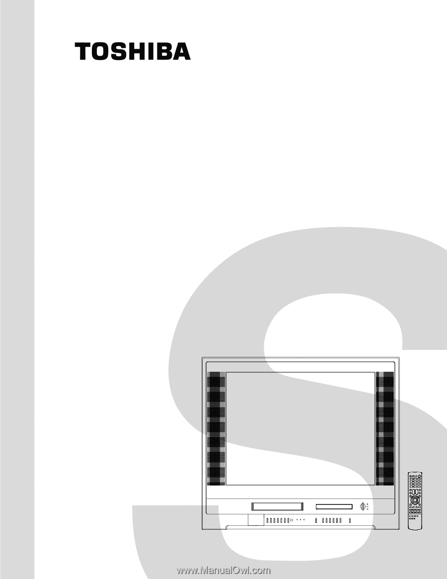
SERVICE MANUAL
COLOR TELEVISION/
VIDEO CASSETTE RECORDER/
DVD VIDEO PLAYER
DOCUMENT CREATED IN JAPAN, April, 2005
MW27F51
FILE NO. 140-200509
(MFR’S VERSION A)