Toshiba P42LSB User Manual
Toshiba P42LSB Manual
 |
View all Toshiba P42LSB manuals
Add to My Manuals
Save this manual to your list of manuals |
Toshiba P42LSB manual content summary:
- Toshiba P42LSB | User Manual - Page 1
- SERVICE MANUAL LCD FLAT PANEL DATA DISPLAY UNIT P42LSA+ P47LSA+ P42LSB P47LSB 1 - Toshiba P42LSB | User Manual - Page 2
31 Function in SERVICE mode 32 Control via RS232C --- Command Protocol list 33 Status Report Z - Commands 37 ASCII - - Hex Conversion Chart 39 FIRMWARE REWRITE 39 DISASSEMBLE 40 P42/47LSA+ / LSB Block Diagram 42 Trouble Shooting 43 P42LSA+ / LSB PARTS List 44 P47LSA+ / LSB PARTS List 45 - Toshiba P42LSB | User Manual - Page 3
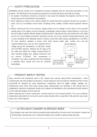
, read the parts list in this manual carefully. The use of substitute replacement parts which do not have the same safety characteristics as specified in the parts list may create shock, fire or other hazards. ULTRAVIOLET DANGER IN SERVICE MODE Eye damage may result from directly viewing the light - Toshiba P42LSB | User Manual - Page 4
product and in the operation manual, precautions are presented to be entrusted to vendors qualified by " Toshiba Lightning and Technology ". Installation and transportation by be observed upon use of this equipment For abnormality or trouble WARNING If during operation the unit emits smoke or odor - Toshiba P42LSB | User Manual - Page 5
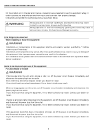
to follow the instructions set-out in the owners manual Any loss of damage caused directly as a result product information manuals & literature. Furthermore, under no circumstances shall Toshiba be Do not twist, bent nor push the LCD panel even momentary, LCD module may be damaged. Disposal When the - Toshiba P42LSB | User Manual - Page 6
the equipment is placed in "stand-by" mode, electricity is still consumed and parts of the circuitry are still "live". If the equipment is not to be power switch and isolate from the main power supply to avoid any unexpected problems, which may cause fire or other damage. Do not block the vent ports - Toshiba P42LSB | User Manual - Page 7
third party damage. Servicing of the equipment and capable of supporting the additional lord with their head or other body part by accident. If the installation is the equipment at places exposed to direct sunshine, or where temperature rises, cut off immediately when trouble or abnormality occurs - Toshiba P42LSB | User Manual - Page 8
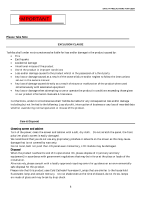
the equipment on a table, unstable base or directly against a wall. Rear access is required for to User Fragile plastic panel The P42LSA+/P47LSA+/P42LSB/P47LSB have a plastic screen and even a small city discard guide. Precautions on Use Connection of a grounded cable Ground the LCD panel in - Toshiba P42LSB | User Manual - Page 9
boards and parts life to become shorter or cause fire to occur. Periodic cleaning of entire equipment is necessary at least once in a year. Always turn off the power when start to do cleanings. GENERAL DESCRIPTIONS FEATURES 42-inch (P42LSA+/P42LSB), 47-inch (P47LSA+/P47LSB) direct view LCD flat - Toshiba P42LSB | User Manual - Page 10
and USER Low power consumption Power consumption of the set is reasonably low as: P42LSA+/P42LSB: 250W P47LSA+/P47LSB: 300W FUNCTION OF PANEL / PUSH buttons Front view of the product LCD Display Panel Control push buttons at side Power Switch stand-by/on Enter Select Menu or Value Select - Toshiba P42LSB | User Manual - Page 11
P42LSA+ / P42LSB DIMENSIONS Size: mm (inch) 122.8 mm (4.84 inch) 619 mm (24.39 inch) 440 mm(17.34 inch) 1026 mm(40.42 inch) 200 mm (7.88 inch) 200 mm (7.88 inch) 200 mm (7.88 inch) 240 mm (9.46 inch) 200 mm (7.88 inch) 11 - Toshiba P42LSB | User Manual - Page 12
P47LSA+ / P47LSB DIMENSIONS Size: mm (inch) 126.2 mm (4.97 inch) 684.4 mm (26.95 inch) 520 mm (20.5 inch) 1139.4 mm (44.86 inch) 200 mm (7.88 inch) 200 mm (7.88 inch) 200 mm (7.88 inch) 280 mm (11 inch) 200 mm (7.88 inch) 12 - Toshiba P42LSB | User Manual - Page 13
FUNCTION OF I/O PANEL Input / Output terminals of LSB model (HD-SDI) Input / Output terminals of LSA+ model VIDEO INPUT Three kinds of Video signal selection as Composite, Y/C or YUV Signal Input Terminal Type CVBS-IN US-Pin (RCA) S-VIDEO-IN S (Y/C) mini DIN YUV (Y Pb/Cb Pr/Cr)-IN YUV mini - Toshiba P42LSB | User Manual - Page 14
FUNCTION OF I/O PANEL Input / Output terminals of LSB model (HD-SDI) Input / Output terminals of LSA+ model Note: 1. BNC, Category-5, Video cables are not included. 2. DVI terminal Analog input is not used. 3. Catrgory-5 input/output are Link only, external signal is not properly be worked. 4. Y- - Toshiba P42LSB | User Manual - Page 15
SELECTION of the SIGNALS Video input VIDEO-1 VIDEO-2 VIDEO-3 Composite Video signal, Y/C (S-VIDEO) Y-Pb-Pr(Y-Cb-Cr) US-Pin (RCA) S connector YUV mini-DIN NTSC/PAL NTSC/PAL NTSC/PAL/up to 480p Note: Y-Pb-Pr (Y-Cb-Cr) terminal can accept up to 720p signal. Higher resolution signals are Supplied - Toshiba P42LSB | User Manual - Page 16
P47LSA+, LSB Size Weight Accessories P42LSA+ / P47LSA+ / P42LSB / P47LSB 42-inch, 47-inch flat panel LCD display unit NTSC/PAL/PC Refer to page 13. 16:9 LCD 39 kg ( 86 lbs ), P47xxxx: 52 kg ( 115 lbs ) Owner's Manual, Power/RGB cables, IR remote control Video Input Y-C Input Y-Cb-Cr Input DVI - Toshiba P42LSB | User Manual - Page 17
5H O 26 720p-60 1280x720 45.00 60.00 74.25 1650 40 220 1280 110 750H 5H 20H 720H 5H O 27 768-60 1360x768 47.72 59.95 84.75 1776 152 176 1360 88 796H 3H 24H 768H 1H O 28 1080i-50 1920x1080 28.13 25.00 74.25 - Toshiba P42LSB | User Manual - Page 18
Replacement (1) (3) Pro-Adjust Area ADJ: Enter to Adjust Mode: Mode selection (memory recall) SPECIAL: Enter Special mode SERVICE: Enter service Pattern To replace the battery inside 1) Push back cover (2) out. 2) Replace with new battery, 2 pieces replaced by an Incorrect type or placed by - Toshiba P42LSB | User Manual - Page 19
• Point the remote control at remote sensor on LCD monitor. About the remote control • Do not drop * ENTER: * EXIT: AUTO: SOURCE: PIP: SWITCH: selection of ON or STAND-BY, lamp and driver power supply are reduced. to enter 1st MENU page Main Menu Item selection Main Menu Item selection Sub Menu - Toshiba P42LSB | User Manual - Page 20
buttons have partially similar operation with old wireless remote control, shown at right. For the adjustments explained from this page up to upper part of page 26, only enlarged, silver colored area, these keys are used. Actually, [MENU], [UP], [DOWN], [LEFT], [RIGHT], [ENTER] and [EXIT] are used - Toshiba P42LSB | User Manual - Page 21
21 - Toshiba P42LSB | User Manual - Page 22
WIRELESS REMOTE CONTROL OPERATION Entering to the adjustment MENU Arrow mark (red) indicates "Selected and Highlighted" When [MENU] button is pushed, Display enters Display Information page as below left, no adjustment functions placed in here. By using [DOWN] key, below right picture appears, this - Toshiba P42LSB | User Manual - Page 23
effect. Auto Adjust is to set Phase and Clock automatically but also manual setting is possible to shut-off this function. Staying in IMAGE page and is an operation guide area where which button is to be used. Before pushing [ENTER] button and after, this operation guide changes its indication - Toshiba P42LSB | User Manual - Page 24
WIRELESS REMOTE CONTROL OPERATION Picture below right shows the COLOR mode, this is to select Gamma Correction for Off-Expand-Compress and Color temperature 3200K/5400K/6500K/9300K and User. At User position, RGB adjustments are possible using User Color R,G,B adjustment selection. To do one of - Toshiba P42LSB | User Manual - Page 25
In COLOR adjust, this is the same to Main Setting but for PiP image. As same as the Adjustments in previous page, any adjustment will reflect to the Main Image when selected. This is because there in only one adjustment value memory for each input. WIRELESS REMOTE CONTROL OPERATION This below - Toshiba P42LSB | User Manual - Page 26
Other Setting Page WIRELESS REMOTE CONTROL OPERATION This page is to do Factory Reset, Picture retention reduction, Language selection, light sensor selection and its value adjustment, Source Automatic detection and DPMS Control. Factory Reset, Picture saturation Reset This page will reset all - Toshiba P42LSB | User Manual - Page 27
FIRMWARE CONFIRMATION OPERATION Firmware confirmation By using left-right button on the wireless remote, push L-L-R-R-L-R to display firmware version on the screen. To escape from this mode, the main rocker power switch needs to be shut-off and turned ON again with an RGB signal connected to - Toshiba P42LSB | User Manual - Page 28
RS232C control When [OFFSET] or [GAIN] Button is clicked in adjust mode the 1st entry will indicate the "red" adjustment or default adjustment. In this case, we use the push [up] / [down] buttons located on the right side of the wired remote control to do an adjustment, then press [ADJ.G] or [ADJ.B] - Toshiba P42LSB | User Manual - Page 29
RS232C CONTROL Press the [ID.SET] button. The master panel whose ID is already assigned will not respond but the 2nd panel without an ID # will activate to have ID.02. The same method is used to assign ID numbers to all the remaining panels. Do not use the same ID number to the different panels, - Toshiba P42LSB | User Manual - Page 30
brightness by Lamp Power control (refer to SERVICE mode). Before this setting, all the video test pattern generator should be used and if computer is the main source, test pattern generating software should Drive Unlike as CRT or DLP type, these LCD monitors have not final stage adjustment such as - Toshiba P42LSB | User Manual - Page 31
mode. Push [WRITE] to memorize. After making such picture effect as 2x2, then, this is how to memorize into Picture Effect Memory. [ADJUST] [SERVICE] [NUMBER] "0" [ENTER] by pressing ENTER several times, USER memory position can be obtained as USER1, USER2 or USER3. After selecting the user position - Toshiba P42LSB | User Manual - Page 32
] then Horizontal and Vertical number key will shift the image. Functions in SPECIAL mode There are several, not so common; adjustments in SPECIAL and also SERVICE modes. This mode can be entered in ADJUST mode and then press [SPECIAL] button. When mode is initiated, all the functions are shown by - Toshiba P42LSB | User Manual - Page 33
selection from [ 0 ] to [ 3 ]. To escape from any operation in SERVICE mode, press [ADJUST] button several times until go back. When using wireless remote this software. When personalized control is necessary, Toshiba will not supply any support software but simply RS232C command Protocol List. - Toshiba P42LSB | User Manual - Page 34
Item Contents Key(CMD**) POWER Turning power ON PWR PON PWR: Alternation switch command PON: Direct switch command An example of Power on for all the cubes: 02h','**','PON','03h (hex ) 53 4C 52 03 02h, (ID), SLG, 03h 02 (ID) 53 4C 47 03 02h, (ID), SLB, 03h 02 (ID) 53 4C 42 03 02h, (ID), VUP, - Toshiba P42LSB | User Manual - Page 35
changes right 02h, (ID), DRG, 03h 02 (ID) 44 52 47 03 Use the above LAYOUT commands for the following functions POSITION CLOCK PHASE Change image direction - Toggle through Change image direction Change image direction Change image direction Memorizes adjusted data Enters SERVICE mode Enters - Toshiba P42LSB | User Manual - Page 36
Mode Function Description ASCII - CMD String ADJ Adjust Mode - to "Back Up" or "Exit" Service 02h, (ID), AJS, 03h SERVICE 0 Enters SERVICE mode Display User Memory picture effect - Toggle 02h, (ID), SVC, 03h 02h, (ID), VN0, 03h 5 Select Aspect Ratio Mode 1:1 Mode FILL Mode 02h, (ID - Toshiba P42LSB | User Manual - Page 37
Mode - then ID Mode Function Description ASCII - CMD String ADJ Adjust Mode - to "Back Up" or "Exit" Service 02h, (ID), AJS, 03h ID ALL Enters ID Mode 02h, (ID), IDA, 03h ID Clear Clears ID 02h may not need) ( Stand-by mode: no power to the back light, LCD panel drive signal/voltage ) 37 - Toshiba P42LSB | User Manual - Page 38
code return by decimal ZPS 5A 50 53 ZMG 5A 4D 47 ZLY 5A 4C 59 ZPH 5A 50 48 ZPV 5A 50 56 ZGR 5A 47 52 ZGG 5A 47 47 ZGB 5A 47 42 ZTM 5A 54 4D ZTL 5A 54 4C ZOR 5A 4F 52 ZOG 5A 4F 47 ZOB 5A 4F 42 ZFH 5A 46 48 - Toshiba P42LSB | User Manual - Page 39
45 Q 51 a 61 m 6D y 79 4 34 F 46 R 52 b 62 n 6E z 7A 5 35 G 47 S 53 c 63 o 6F 6 36 H 48 T 54 d 64 p 70 7 37 I 49 U 55 e 65 improvement or new Operation System is made to the panel, we replace an E-PROM. The LSA+/LSB models have an RS232C input - Toshiba P42LSB | User Manual - Page 40
¥ LCD Holder --- rd_monitor_LHA_42&47.hex --- rd_monitor_LSA_27&32.hex --- rd_monitor_LSA+_42&47.hex this new file should be copied under this sub-directly And be re-named, then the FlashRom_8.txt The old inside, LSA+_42&47 will be gone and new LSA_27&32 is replaced and becomes active. To rewrite, - Toshiba P42LSB | User Manual - Page 41
and 47-inch parts locations. Both models are using the same internal mechanism which is indicated by red color, only two support bars are attached at different locations. Handles are also written, the picture is indicating that These handles are come in handy when servicing. Place the LCD monitor - Toshiba P42LSB | User Manual - Page 42
P42/47LSA+/LSB Block Diagram Trouble shooting P42LSA+ / P47LSA+ 42 Power Supply 5V: not used 18V: Main same monitors in series, an external control signal to this RJ45 may not work properly. When servicing, be sure to touch a metal chassis to discharge static electric before touching to any circuit - Toshiba P42LSB | User Manual - Page 43
the power supply. If fuse is brown, replace it. If fuse brown again, The power supply unit has problem inside. Replace the power unit with the same type. , the LCD drive circuit or LCD might be damaged. In this case, LCD panel assembly replacement is necessary. Please contact the Toshiba dealer for - Toshiba P42LSB | User Manual - Page 44
P42LSA+ Mechanism and Parts 44 - Toshiba P42LSB | User Manual - Page 45
P47LSA+ Mechanism and Parts 45 - Toshiba P42LSB | User Manual - Page 46
46
-
 1
1 -
 2
2 -
 3
3 -
 4
4 -
 5
5 -
 6
6 -
 7
7 -
8
-
9
-
10
-
11
-
12
-
13
-
14
-
15
-
16
-
17
-
18
-
19
-
20
-
21
-
22
-
23
-
24
-
25
-
26
-
27
-
28
-
29
-
30
-
31
-
32
-
33
-
34
-
35
-
36
-
37
-
38
-
39
-
40
-
41
-
42
-
43
-
44
-
45
-
46
 |
 |
1
-
SERVICE MANUAL
LCD FLAT PANEL DATA DISPLAY UNIT
P42LSA+
P47LSA+
P42LSB
P47LSB