Toshiba Qosmio X875-Q7190 User Guide - Page 49
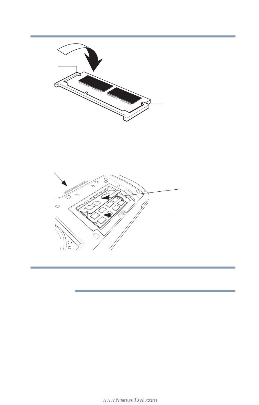
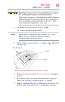
Sample Illustration Pressing down on the memory module
 |
View all Toshiba Qosmio X875-Q7190 manuals
Add to My Manuals
Save this manual to your list of manuals |
Page 49 highlights
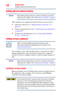
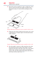
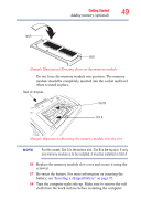
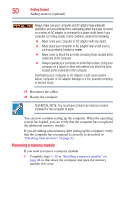
Getting Started 49 Adding memory (optional) latch latch (Sample Illustration) Pressing down on the memory module Do not force the memory module into position. The memory module should be completely inserted into the socket and level when secured in place. Back of computer Slot B Slot A (Sample Illustration) Inserting the memory module into the slot NOTE For this model, Slot A is the bottom slot. Slot B is the top slot. If only one memory module is to be installed, it must be installed in Slot A. 16 Replace the memory module slot cover and secure it using the screw(s). 17 Re-insert the battery. For more information on inserting the battery, see "Inserting a charged battery" on page 95. 18 Turn the computer right side up. Make sure to remove the soft cloth from the work surface before restarting the computer.
-
 1
1 -
2
-
3
-
4
-
5
-
6
-
7
-
8
-
9
-
10
-
11
-
12
-
13
-
14
-
15
-
16
-
17
-
18
-
19
-
20
-
21
-
22
-
23
-
24
-
25
-
26
-
27
-
28
-
29
-
30
-
31
-
32
-
33
-
34
-
35
-
36
-
37
-
38
-
39
-
40
-
41
-
42
-
43
-
 44
44 -
 45
45 -
 46
46 -
 47
47 -
 48
48 -
 49
49 -
 50
50 -
 51
51 -
 52
52 -
 53
53 -
 54
54 -
55
-
56
-
57
-
58
-
59
-
60
-
61
-
62
-
63
-
64
-
65
-
66
-
67
-
68
-
69
-
70
-
71
-
72
-
73
-
74
-
75
-
76
-
77
-
78
-
79
-
80
-
81
-
82
-
83
-
84
-
85
-
86
-
87
-
88
-
89
-
90
-
91
-
92
-
93
-
94
-
95
-
96
-
97
-
98
-
99
-
100
-
101
-
102
-
103
-
104
-
105
-
106
-
107
-
108
-
109
-
110
-
111
-
112
-
113
-
114
-
115
-
116
-
117
-
118
-
119
-
120
-
121
-
122
-
123
-
124
-
125
-
126
-
127
-
128
-
129
-
130
-
131
-
132
-
133
-
134
-
135
-
136
-
137
-
138
-
139
-
140
-
141
-
142
-
143
-
144
-
145
-
146
-
147
-
148
-
149
-
150
-
151
-
152
-
153
-
154
-
155
-
156
-
157
-
158
-
159
-
160
-
161
-
162
-
163
-
164
-
165
-
166
-
167
-
168
-
169
-
170
-
171
-
172
-
173
-
174
-
175
-
176
-
177
-
178
-
179
-
180
-
181
-
182
-
183
-
184
-
185
-
186
 |
 |